|
Standard Product Family
Summaries - PMR Mobiles
|
|
|
Note 1.
The chronological order is approximate,
due to the time overlaps of various design
programs
|
Note 2.
This list summarises the standard
product ranges, and does not include (the
many) customer specific variations
|
|
|
PTC102-103
(1946)
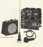 Although this equipment
was not the absolute first Pye Telecom
product, it was the Company's first generation
of commercial business two-way radio
transmitter & receivers. The family
of Amplitude Modulated (AM) equipment was
designed between 1944 - 1946 and first
publicised in November 1946. The
British Home Office was the first user of the
PTC102/103 equipments for Police patrol cars
in 1946. A matching
base station was designed at the same time (PTC104-105-106),
and
also
a
series
of
point-to-point VHF link equipment. Although this equipment
was not the absolute first Pye Telecom
product, it was the Company's first generation
of commercial business two-way radio
transmitter & receivers. The family
of Amplitude Modulated (AM) equipment was
designed between 1944 - 1946 and first
publicised in November 1946. The
British Home Office was the first user of the
PTC102/103 equipments for Police patrol cars
in 1946. A matching
base station was designed at the same time (PTC104-105-106),
and
also
a
series
of
point-to-point VHF link equipment.
The mobile
equipment was remote mounted and consisted of
four main units on a shock absorbing cradle.
These were receiver,
transmitter,
modulator/public
address amplifier and power supply
unit. The first three units were mounted
on top of the power supply. The
individual units used the type number series
PTC500 & 600 etc. A
choice of operator remote control units were
available, a large one with an internal
loudspeaker for use with a hand microphone and
a
smaller one for use with a telephone
handset. The mechanical construction of
the radio units used silver plated brass
chassis, the equipment exterior was finished
in black wrinkle paint finish, and utilised a
microphone similar to that of the war-time
Wireless Sets No. 18 (also designed by
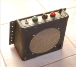
Pye). See the large loudspeaker control
box at right.
The product was replaced by the
PTC114/115.
Production life: 1946 - 1950
Standard frequency range: 77 - 83 MHz
and 94 - 100 MHz, (27 - 125 MHz by special
order)
Transmitter RF output: 12 Watts AM
Primary model variants:
PTC102 simplex operation, PTC103 duplex
operation, 6 Volt and 12 Volt versions, range
of control units
Product sales leaflet: yes
to follow
Extract from technical manual: Cover,
Page1,
Page2,
Page3
|
|
|
|
PTC107 (1946)
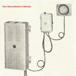 The PTC107 was a first
generation VHF Marine Mobile based on the same
modules also used in the PTC102/3, and was the
first licensed business two-way radio system
in the United Kingdom. The PTC107
equipments were installed in a fleet of tugs
on the river Tyne before the first land mobile
radio system was licensed using the PTC102 for
Camtax Taxis in Cambridge.
The marine equipment was constructed in a
flat, shock protected bulkhead mounting case,
and used a waterproof remote control unit type
PTC534 with separate loudspeaker and telephone
handset.
The equipment was also suitable for
mounting in locomotives and was installed in
British Rail shunting engines using a custom
die-cast protective outer casing. The PTC107 was a first
generation VHF Marine Mobile based on the same
modules also used in the PTC102/3, and was the
first licensed business two-way radio system
in the United Kingdom. The PTC107
equipments were installed in a fleet of tugs
on the river Tyne before the first land mobile
radio system was licensed using the PTC102 for
Camtax Taxis in Cambridge.
The marine equipment was constructed in a
flat, shock protected bulkhead mounting case,
and used a waterproof remote control unit type
PTC534 with separate loudspeaker and telephone
handset.
The equipment was also suitable for
mounting in locomotives and was installed in
British Rail shunting engines using a custom
die-cast protective outer casing.
The product
was replaced by the PTC114/115 and later by
the Marine Ranger series.
Production life: 1946 - 1950
Standard frequency range: 77 - 83 MHz
and 94 - 100 MHz, (27 - 125 MHz by special
order)
Transmitter RF output: 12 Watts AM
simplex only
Primary model variants: 6
Volt and 12 Volt versions
Product sales leaflet: yes
to follow
|
| Top of page |
|
PTC108
(1948)
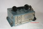 The PTC108 was Pye Telecom's first under-dash
mounting mobile, and one of the very first under-dash
mounted equipments in the world. It used
the same first generation technology as the
PTC102/3/4.
Discussions in October 2002 with the
original designer reveals that the first
prototype radio was unofficially created in
1948 during an unplanned lull in work on the
Pye Instrument Landing System (ILS), by taking
the receiver unit from the PTC102, building a
low powered transmitter on a small
chassis beside it, and adding a psu using a
small rotary transformer. When the
commercial potential was realised a simple
front panel and a sheet steel
wrapper were drawn up, some simple
controls added and the first Pye Telecom VHF
PMR mobile to be finished in Dimenso Blue
paint was born.
See inside
top view and underside
view. Unlike the
PTC102, this was a simplex-only equipment,
operating on a press-to-talk basis and using a
telephone handset instead of a hand
microphone. The
example
equipment
pictured
above
has
components dated June 1950.
The product was replaced by the PTC116
Reporter Series.
Production life: 1948 - 1952
Standard frequency range: 27 - 132 MHz
Transmitter RF output: 3 - 5 Watts AM
Primary model variants:
Transportable version, extended control
version, mains powered version, 6 Volt and 12
Volt dc versions
Product sales leaflet:
yes to follow
Extract from technical manual: Cover,
Page1,
Page2,
Page3,
Page4
|
|
|
|
|
PTC114
& PTC115 (1949)
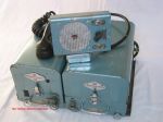 The Pye
PTC114 & 115 series was a product
replacement for the PTC102, providing remote
mount operation and fairly high RF power
output of 15 W. It was
designed before the lower powered PTC112 shown
below and intended to meet the new British
Home Office specifications for Police
mobiles. This was the second generation
mobile radio technology. The Pye
PTC114 & 115 series was a product
replacement for the PTC102, providing remote
mount operation and fairly high RF power
output of 15 W. It was
designed before the lower powered PTC112 shown
below and intended to meet the new British
Home Office specifications for Police
mobiles. This was the second generation
mobile radio technology.
The PTC102/3
first
generation
mobile
equipment was
of expensive silver-plated construction and
also used war surplus components, which
ultimately began to reduce in availability.
Also, the future requirement for a
reduction in channel spacing from 100KHz to
50KHz required higher selectivity and greater
component stability. As a result, this
second generation two-way radio technology
platform was designed between 1947 and 1950.
The
PTC114/115 equipment consists of two separate
transmitter and receiver units, both mounted
as plug-in modules on to a pre-wired
cradle assembly. Each separate transmitter
and receiver unit has a rotary
transformer for HT generation which
can be seen in this interior top view.
In 1953, a
PTC115 high-band equipment was fitted into the
Ford Zephyr car of HRH Prince Philip and later
into the De Havilland Heron aircraft of the
Queen's Flight. In 1954 the equipment
was re-fitted into HRH's Aston Martin Lagonda.
The product was replaced by the
PTC2201/2 Ranger Fifteen Series 15 Watt remote
mounts.
Production life: 1949 -
1956
Standard frequency range:
PTC114, 60 - 100 MHz, PTC115, 100 - 185
MHz
Transmitter RF output: 10 -15
Watts AM
Primary model variants:
6, 12 or 24 Volt dc operation, 1 or 2 channel
operation, PTC114Z-115Z
later version using QQV03/20A PA valve.
Extract
from
product sales leaflet
|
|
|
|
|
PTC112-113
(1950)
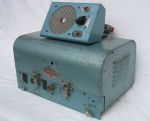 The PTC112/113
was a second generation, low powered, 1 Watt
AM, single unit remote mount equipment.
It was supplied with The PTC112/113
was a second generation, low powered, 1 Watt
AM, single unit remote mount equipment.
It was supplied with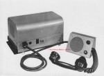 a simple control
box/loudspeaker and telephone handset similar
to the PTC114 above but not fitted with an
on/off switch for the loud-hailer function
provided by the modulator section of the
PTC114. a simple control
box/loudspeaker and telephone handset similar
to the PTC114 above but not fitted with an
on/off switch for the loud-hailer function
provided by the modulator section of the
PTC114.
The PTC112 was
developed by Martyn O'Dwyer in 1949 and the
product started production in early 1950.
Effectively, the PTC112/113 is the PTC114
receiver unit designed by George Smith, with a
low power transmitter mounted on the
same chassis. Early internal
photographs of prototypes show the hand-made
modifications to a PTC114 chassis. See
photograph of prototype at right.
It was
intended as a lower cost equipment than its
contemporary, the higher power PTC114/115, and
directed at commercial users rather than
Government Agencies and Police, who were the
target audience for the PTC114/115. The
PTC112/113 remote mount mobile was fitted to
the car used by Donald Campbell to set the
land speed record.
The PTC112
equipment pictured above left has components
dated October 1951and is shown with the
control box from a PTC114. See Top side
view and Underside
view.
The
product
was
replaced
by
the
PTC2101/2
Ranger
Series 5 Watt remote mounts
Production
life: 1950 - 1956
Standard frequency range:
PTC112, 27 - 132 MHz, PTC113, 156 - 184
MHz
Transmitter RF output: PTC112, 4 -5
Watts AM, PTC113, 3 -5 Watts AM
Primary model variants: Wide and
narrow IF bandwidth versions, 6 volt and
12 Volt dc versions
|
| Top of page |
|
|
Reporter
Series, PTC116-117 etc. (1951)
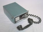 A long running series of low power, dash
mounted AM mobiles first promoted in July
1951. The Pye Reporter
was introduced to provide a low cost, front
mounted radiotelephone using the second
generation technology platform, and sold for
the price of £80 throughout its life.
As with the PTC112, the chassis layout bore a
strong similarity to the PTC114 receiver unit,
but with the addition of a low power
transmitter. See top view,
and underside
view. Unlike the PTC112
and PTC114, the Reporter did not use a rotary
transformer to generate the valve HT voltages,
but used a vibrator PSU to convert the 12V DC
supply to AC.
A great many variants of the
Reporter were created over its long production
life time. The core product was a single
channel dash mount. However, 1, 3 and 6 channel
variants were also produced by the Pye
Finglas Dublin factory, together with the
AM5D; a later version with a transistorised
power supply. The equipment also had a
long production life at Pye Australia
throughout the 1950s.
A specially adapted Pye Reporter was fitted to
Donald Campbell's boat 'Bluebird' in September
1956 when he set the world water-speed record
of 225.63 MPH. Transportable Reporters
were used on the various boats monitoring the
speed run and also on the shore.
The sample equipment shown above
has components dated 1953.
Production life: 1951 - 1965
Standard frequency range: 32.5 - 184
MHz in 13 different frequency bands
Transmitter RF output: 1
- 2.5 Watts
Primary model variants: PTC6/116/117
6
channel,
PTC118/119
mains/dc
powered,
PTC126/127 transportable, PTC128/129 ??,
PTC136/137 motorcycle, PTC718/719 ??,
PTC116/7029 Pye Partridge rack mounting 60 - 100
MHz 24 V dc aircraft version, PTC170 is PTC116/7
with transistorised PSU, Reporter versions
with suffix X in type number use a fist
microphone instead of the original telephone
handset.
Product sales leaflet: Page 1,
Page 2
|
|
|
|
Transistor
Reporter
AM5D (1963)
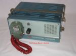 The Transistor Reporter
AM5D was a small dash mount mobile, and in
technology terms was a cross between the
PTC116 Reporter, the PTC2001 Ranger and the
AM10D Cambridge and was mainly sold in the
Republic of Eire. It was
initially given the type number P.T. D-15
which was then changed to AM5D The Transistor Reporter
AM5D was a small dash mount mobile, and in
technology terms was a cross between the
PTC116 Reporter, the PTC2001 Ranger and the
AM10D Cambridge and was mainly sold in the
Republic of Eire. It was
initially given the type number P.T. D-15
which was then changed to AM5D
The product was designed and manufactured by
the Pye subsidiary Telecommunications,
Finglas, Dublin, who produced a wide range of
Pye Telecom equipments from antennas to test
equipment to high power transmitters, etc.
The product used valve technology for the
receiver and transmitter, and had a
transistorised power supply. The
receiver circuits would appear to have been
taken from the Ranger PTC2001, the transmitter
from the PTC116 Reporter and the dc-dc
inverter power supply from
the Cambridge. The
product pictured here has the serial number
000022.
See comparison
photo with the Cambridge dash mount.
Production
life: Withdrawn from the Pye Telecom UK
sales catalogue in 1965
Standard
frequency range:
Transmitter RF
output:
Primary
model variants:
Product
sales
leaflet: yes to follow
|
| Top of page |
|
Ranger
Series PTC2000/8000 etc. (1955)
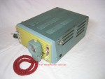 The
Pye Ranger introduced the third generation of
mobile and fixed station circuit design, and
evolved into a very large product family which
included AM, FM, dash mount, short remote,
long remote mounted versions, and marine
equipment. This third generation design was
suitable for all channel spacings between
20KHz and 120KHz, which enabled the Company to
supply it to a wide range of international
type approval specifications, including the
difficult Canadian market. The dash
mount Ranger was initially designated as the
PTC143, and the series type number designation
later changed to PTC2000 series for AM and
PTC8000 series for FM. The
Pye Ranger introduced the third generation of
mobile and fixed station circuit design, and
evolved into a very large product family which
included AM, FM, dash mount, short remote,
long remote mounted versions, and marine
equipment. This third generation design was
suitable for all channel spacings between
20KHz and 120KHz, which enabled the Company to
supply it to a wide range of international
type approval specifications, including the
difficult Canadian market. The dash
mount Ranger was initially designated as the
PTC143, and the series type number designation
later changed to PTC2000 series for AM and
PTC8000 series for FM.
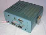
Each
equipment was made up of 3
individual chassis (receiver,
transmitter & PSU) which allowed great
flexibility and enabled a matching fixed
station equipment to be developed from the
common chassis assemblies. This
construction can be more easily seen in the
large 25 Watt boot mount version, shown below
with covers
removed. See also 25
Watt remote with control unit. It
is interesting to note that as late as 1962
the Ranger and F27AM fixed stations were
still being fitted with the old wartime 'Pye
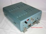
coaxial connectors'. The smaller 5
Watt remote mount version is also shown to the
right. See top
side and underside
views.
 The
5 Watt dash and remote
versions were replaced by the Cambridge series
and the 25 Watt remote by the Vanguard
series and the Continental The
5 Watt dash and remote
versions were replaced by the Cambridge series
and the 25 Watt remote by the Vanguard
series and the Continental
Production life: 1955 - 1963
Standard frequency range: 25
- 174 MHz in 9 bands
Transmitter RF output: 5 Watts AM, 15
Watts AM, 25 Watts AM, 10 Watts FM, 25 Watts FM
Primary model variants:
PTC2001/2, PTC2107, PTC2201/2, PTC2207,
PTC8001/2, PTC8101/2, PTC2022, PTC2012,
PTC143/PTC2002YN, PTC8001/2, PTC8007, PTC8207,
PTC8302, PTC8306, RNN ZOK 01/00 (Netherlands
Navy).
Product sales leaflet, model PTC2001/2:
Page
1, Page
2, Page
3, Page
4
|
|
|
|
Vanguard
Series
AM25/FM25
etc (1962)
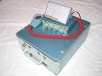 The Pye
Vanguard was a family of high power remote
mount mobiles and was the first of the fourth
generation of mobiles which included the
Cambridge series. The design used a sealed
block LC filter for receiver IF
selectivity, as opposed to using
distributed interstage band pass filtering by
transformers. See inside
top view and underside
view of an AM25B valve receiver version. The Pye
Vanguard was a family of high power remote
mount mobiles and was the first of the fourth
generation of mobiles which included the
Cambridge series. The design used a sealed
block LC filter for receiver IF
selectivity, as opposed to using
distributed interstage band pass filtering by
transformers. See inside
top view and underside
view of an AM25B valve receiver version.
The
Vanguard was originally designed to meet a
requirement specification issued by the UK
Home Office. Pye won the contract with
the PT B10AM design which started production
in 1962, and following the success of the
product, a range of standard commercial
versions were created. See the pictorial
'Story of the Vanguard' in the Photo Gallery
section.
The initial
PT B10AM and AM25B models were valve
designs with transistors used in the audio and
power supply circuits. The later AM25T
and FM25T versions used the same fully
transistorised receivers as the Cambridge
AM10/FM10 series. Transmit powers of 20
Watts AM and 60 or 100 Watts FM were
available. A 30 Watt UHF FM version, the
U30FM, was also produced.
The product
family was first introduced as the PT B10AM,
PT B25AM, PT B25FM and PT B100FM, but was
later renamed Vanguard AM25B, AM25T and FM25B.
The designation B100FM remained for the 100
Watt version. Various
marine variants were introduced, as was a
fixed station version in a distinctive green
cabinet.
The
Vanguard product was partly replaced by the
Westminster W25FM and W30AM series remote
mounts, but the Company did not produce high
power RF output mobiles again until the 100
Watt PMR2 model of the early 1970s, and the 50
Watt M206 of the late 1970s.
Production life: 1962 - 1970
Standard frequency range:
VHF 25 - 174 MHz, UHF 450 - 470 MHz
Transmitter RF output: AM25T
20W, FM25B 60W, B100FM 100W
Primary model variants: B10AM,
AM25B, AM25T, FM25B, B100FM, U30FM, VM, etc.
Product sales leaflet,
model AM25T: Page 1,
Page2
|
|
|
|
Cambridge
Series AM10/FM10 etc. (1963)
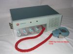 The
Pye Cambridge series of dash mount and boot
mounted equipments was a very successful
family of fourth generation mixed technology
equipment design, with all
solid state receivers and valve
transmitters giving RF power
outputs of 5, 15, and 25 Watts. See top view
and underside
views. Initially designated the
PT. D10 AM, the type number was changed to
AM10D etc. in 1963. The
higher power "Pye Continental" FM models BC25
and DC25 were originally given the designation
B20FM and D20FM. A UHF
remote mount was also created, based on
the low-band version but equipped with an
extra receive down-converter with made the
receiver a triple superhet. The
Pye Cambridge series of dash mount and boot
mounted equipments was a very successful
family of fourth generation mixed technology
equipment design, with all
solid state receivers and valve
transmitters giving RF power
outputs of 5, 15, and 25 Watts. See top view
and underside
views. Initially designated the
PT. D10 AM, the type number was changed to
AM10D etc. in 1963. The
higher power "Pye Continental" FM models BC25
and DC25 were originally given the designation
B20FM and D20FM. A UHF
remote mount was also created, based on
the low-band version but equipped with an
extra receive down-converter with made the
receiver a triple superhet.
The transistorised
receiver designed for the Cambridge
series was widely used in both the higher
powered Vanguard family, and also in the
matching fixed station receivers of the time.
The product was replaced by the Westminster
series of AM and
FM dash and remote mounts.
Production life: 1961 - 1970
Standard frequency range: 25
- 174 MHz in 10 frequency bands
Transmitter RF output: Cambridge, 5-7
Watts AM, 15 Watts FM, Continental, 25
Watts FM
Primary model variants:
AM10B, AM10D, AM10P, AM10MC, FM10B, FM10D,
FM10P, FM10MC, U10B, BC25, DC25, etc.
Product sales leaflet,
model AM10D: Page1,
Page2
|
|
|
|
Westminster
Series W15/W20/W25/W30 etc. (1967 etc)
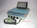 The Westminster was the the
fifth generation mobile technology platform
since 1947 and a major family of
all-transistor PMR mobiles (except the PA
valve of the W30). First
introduced in 1967, the Westminster was
claimed to be the worlds first
all-semiconductor PMR mobile, and more than
120,000 were produced. The Westminster was the the
fifth generation mobile technology platform
since 1947 and a major family of
all-transistor PMR mobiles (except the PA
valve of the W30). First
introduced in 1967, the Westminster was
claimed to be the worlds first
all-semiconductor PMR mobile, and more than
120,000 were produced.
The
standard range covered AM and FM VHF models in
front
mount, remote
mount, transportable,
marine, motorcycle and universal mounting
versions, plus various ancillaries such as battery
chargers, power supplies, carrying
cases etc.
The
equipment construction although hard-wired,
was essentially modular, using small PCBs for
each of the main circuit functions mounted on
a double sided aluminium platform
chassis. Many common PCB
and circuits were shared with the fixed
stations of the time. See
top
side and underside
view of an AM Westminster short remote
mount. The product also marked the
change in product colour scheme from Dimenso
blue hammer finish paint to a blue/grey
textured acrylic.
In addition
to the range of standard VHF 6-15 Watt dash
and remote mounting equipments shown above,
other higher power or specialist versions also
evolved, including the W25FM, W30AM, LW15FM
radiophone, W15U and W20U UHF. These
models all utilised a longer chassis and
mounting cradle than the standard short VHF
models.
The
product was replaced by the M200 Olympic
series of AM and FM dash and remote mounts,
which overlapped in production dates.
Production life: 1967 - 1978
Standard frequency range: 25
- 174 MHz, (Pye A, B, C, P, E, G, H bands), 402
- 435 MHz (T3), 450 - 470 MHz (U) A, B,
Transmitter RF output: W15FM - 15 Watts
Primary model variants:
W15AM & W15FM VHF, W15U & W20U UHF,
W25FM, W30AM, LW15FM etc
Product sales leaflet, model
W15FM DS: Page1, Page2
|
|
|
|
Whitehall
W20AM/FM
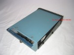 The
W20AM/FM Whitehall was an AM/FM
remote mount mobile initially created for the
British Home Office at a time when some British
County Police Forces used AM transmission and
others used FM transmission. The
Whitehall allowed UK police vehicles to
communicate with the local network
infrastructure in any county when operating away
from their home area. The W20 equipment
was subsequently purchased by the Ministry of
Defence for use by the RAF and for various other
projects such as nuclear weapons convoys etc. The
W20AM/FM Whitehall was an AM/FM
remote mount mobile initially created for the
British Home Office at a time when some British
County Police Forces used AM transmission and
others used FM transmission. The
Whitehall allowed UK police vehicles to
communicate with the local network
infrastructure in any county when operating away
from their home area. The W20 equipment
was subsequently purchased by the Ministry of
Defence for use by the RAF and for various other
projects such as nuclear weapons convoys etc.
The equipment was based on the Westminster
design printed circuit boards but used
a different and larger chassis, lids and
mounting cradle and generated
slightly higher transmit power. The
control box was also a dedicated design.
See top
side view and underside
view.
Production
life:
Standard
frequency range:
Transmitter RF
output:
Primary
model variants:
Product
sales
leaflet: yes to follow
|
| Top of page |
|
VHF-UHF Repeater
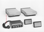 A Westminster series
configuration of two remote mount mobiles, one
simplex VHF and one duplex UHF, to provide a
flexible cross-band mobile repeater
station. Four separate operating modes
were available; 1 - automatic 2-way talk-through
between VHF and UHF systems, 2 - manually
controlled UHF duplex base station using just
the UHF set, 3 - normal simplex VHF operation
and 4 - UHF on-site automatic talk-through using
just the duplex UHF set. A Westminster series
configuration of two remote mount mobiles, one
simplex VHF and one duplex UHF, to provide a
flexible cross-band mobile repeater
station. Four separate operating modes
were available; 1 - automatic 2-way talk-through
between VHF and UHF systems, 2 - manually
controlled UHF duplex base station using just
the UHF set, 3 - normal simplex VHF operation
and 4 - UHF on-site automatic talk-through using
just the duplex UHF set.
Originally designed to a UK Home Office
specification for Police communications, the
system combined the features of the VHF and UHF
equipments into one installation using a common
control unit and telephone handset. This
system was first configured using the
W20AM/FM Whitehall mobile as the VHF equipment
and a duplex W15U as the UHF equipment.
Later, the system was also available using the
W25FM as the VHF equipment.
Production life:
Standard frequency
range:
Transmitter RF
output: UHF 5 Watts, VHF 20 Watts AM/FM using
Whitehall equipment or 30 Watts FM using W25FM
equipment
Primary
model variants:
Product sales
leaflet: yes to follow
|
| Top of page |
|
Motafone
MF5AM (1972)
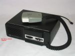 The
MF5AM Motafone was a single product,
lightweight, low cost, all-transistor AM
mobile, designed primarily for the UK market,
and was the forerunner to the FM Europa
series. This sixth
generation technology mobile product
introduced
the
use
of
integrated
circuits
and reduced the
component count compared to the
Westminster. It was designed to be a
limited feature dash mount
only product, positioned below
the AM Westminster, at a time when cheaper
competing products were taking market share
from Pye Telecom. The
MF5AM Motafone was a single product,
lightweight, low cost, all-transistor AM
mobile, designed primarily for the UK market,
and was the forerunner to the FM Europa
series. This sixth
generation technology mobile product
introduced
the
use
of
integrated
circuits
and reduced the
component count compared to the
Westminster. It was designed to be a
limited feature dash mount
only product, positioned below
the AM Westminster, at a time when cheaper
competing products were taking market share
from Pye Telecom.
The
construction used an aluminium chassis with a
separate vinyl-clad sleeve wrapper and front
panel. An internal loudspeaker was
fitted and the audio output power was
limited. See top side
view and underside
view.
The
product was replaced by the MF6AM Reporter AM
dash mount.
Product comparison photographs to
follow
Production life:
Standard frequency range: 68
- 88 MHz (E band), 118 - 136 MHz (C band), 138 -
141/105 - 108 MHz (Mid band, 148 - 174 MHz (A
band)
Transmitter RF output: 2.5 Watts
Primary model variants:
Pye Pilot, aircraft band version for
gliders etc.
Product sales leaflet, model
MF5AM: Yes to follow
|
|
|
|
Europa
Series MF5FM/MF25FM/MF5U (1971)
 A
medium scope family of low cost,
all-transistor FM mobiles, positioned in the
market below the FM Westminster. It
was
a dash-mount only product - although
transportable and desk-top PSU mounted
versions were also produced. A
medium scope family of low cost,
all-transistor FM mobiles, positioned in the
market below the FM Westminster. It
was
a dash-mount only product - although
transportable and desk-top PSU mounted
versions were also produced. The Europa family was part of a drive to
lower the costs of Pye Telecom equipment by
reducing the number of printed circuit boards
and also the amount of interconnect wiring
between them. Along with
the MF5AM, this sixth generation technology
series increased the packing
density of components compared to the
Westminster, and introduced the use of
integrated circuits into Pye Telecom mobiles.
The
construction used three aluminium die-cast
pieces to form the two sides and rear panel of
the case, with sheet steel top and bottom
covers plus a sheet steel front panel coated
with thick vinyl-clad padding as a safety
feature. See inside view showing the receiver
PCB and the transmitter
PCB.
These FM products
were initially called "Motafone" along with
the UK MF5AM product, but the MF5FM, MF25FM
and MF5U were quickly renamed Europa to
signify their wider international market
suitability and targeting.
A wall
mounted fixed station was later derived
from the series, and the original MK1 version
of the first UK Amateur VHF repeater GB3PI was
based on two MF25FM circuit boards.
The product was replaced by the M290
series of AM and FM dash mounts.
Production life: 1971 - ?
Standard
frequency range:
Transmitter RF
output:
Primary
model variants:
Product sales leaflet, model MF25FM: yes
to follow
|
|
|
|
PMR2FM
(1971)
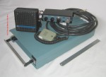 The PMR2FM was a
single product high power (100 Watts) remote
mount FM transceiver, manufactured in a
limited range of frequency bands. It was
designed expressly for the non-European export
market, to compete against equipments such as
the Motorola Micor. The Micor featured
very high transmit power transmitter, and also
had a receiver with very high intermodulation
protection and adjacent channel selectivity. The PMR2FM was a
single product high power (100 Watts) remote
mount FM transceiver, manufactured in a
limited range of frequency bands. It was
designed expressly for the non-European export
market, to compete against equipments such as
the Motorola Micor. The Micor featured
very high transmit power transmitter, and also
had a receiver with very high intermodulation
protection and adjacent channel selectivity.
The PMR2FM equipment used a hybrid main mother
board with some plug-in daughter boards.
The electronics were all mounted between two
die cast aluminium covers, the lower of which
also acted as the transmitter heat sink.
Many of the circuits and constructional
techniques were the forerunners of the FM
Olympic series. See PMR2 inside
top view.
During the early 1970s, when the Pye
Ditton Works Newmarket Road site was full to
bursting point, various sections from the
development laboratories were spun off to
external locations. The PMR2FM equipment
was designed by the newly created FM Mobile
Lab, one of these
'Boutique' Labs first established
at the old Ekco Southend factory and led by
Hugh Hamilton (of AM10 Cambridge and W15
Westminster fame). Later, this group
moved to Gloucester Street, Cambridge and
became Mobile Lab 4, where it designed the
M202 and M212 FM Olympics, the M252 Pegasus,
the M206 remote mount, and later at St.
Andrews Road the first of the MX290 series
mobiles, the MX294.
The PMR2 product was
partially replaced by the 40-50 Watt M206
remote mount simplex version.
Note that due to human error, the equipment
above was photographed with the wrong
loudspeaker unit (a later M206 10 Watt speaker
which used the same moulding tool but a
different colour and a different LS drive
unit). The PMR2 loudspeaker units were
moulded in blue and not black.
The control box shown is also a later
prototype used for Lab testing of the M206A
Production life: 1971 - 1978
Standard
frequency range:
Transmitter RF
output: 100 Watts
Primary
model variants: Remote mount
only
Product sales leaflet, model PMR2FM:
yes to follow
|
Top of
page
|
|
Olympic/Beaver
Series M200 etc. (1973 etc)
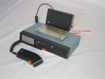 A major family of crystal
controlled seventh generation mobiles, which
used mother/daughter board construction with
plug-in circuit boards and extensive use of
thick-film hybrids, integrated
circuits and TX RF power
modules. The series was intended to
replace the Westminster family and to include
both dash mount and remote mount products in
VHF, UHF, FM and AM. However not all
parts of the Olympic series were ever
implemented and overall it had a more
complicated history than many of the mobile
product families. A major family of crystal
controlled seventh generation mobiles, which
used mother/daughter board construction with
plug-in circuit boards and extensive use of
thick-film hybrids, integrated
circuits and TX RF power
modules. The series was intended to
replace the Westminster family and to include
both dash mount and remote mount products in
VHF, UHF, FM and AM. However not all
parts of the Olympic series were ever
implemented and overall it had a more
complicated history than many of the mobile
product families.
The Olympic dash mount mechanical
construction used an aluminium die cast frame
with integral heat sink and die cast
lids. See
top side internal view of single channel
M202 FM dash mount.
A common frame was used for the M202 and M212
FM models and a different frame for the M201
AM model.
For remote mount Olympics, an entirely
different construction was planned but only
the M203 from the original remote mount series
was ever implemented. The M203 AM remote
mount mobile used a pressed steel chassis
frame, heat sink and lids based on the design
of the original M204/M206/M214/M216 equipments
(which never went into
production). See
top side internal view of M203 AM remote
mount. Note that in common with
the original planned FM remote mount Olympics
the M203 allowed for a twin head receiver
option. The dash mount
Olympic products were all similar in size and
aspect ratio to the Europa FM mobile and
could accept the same front-panel
plug-in tone signaling modules.
The original remote mounts were intended to
use an internally mounted signaling module
from the P5000 portable range.
Servicing for all models was
achieved by module replacement, and a
range of extender cards used to allow in-situ
fault-finding
of
the vertically mounted circuit boards.
The Olympic series was intended to be the
replacement for the Westminster series (which
had gradually become expensive to manufacture
due to the multi-PCB construction and cable
form interconnect wiring). The intention
was that the use of the motherboard/daughter
board concept to eliminate assembly wiring,
plus thick-film hybrids and integrated
circuits to provide a lower component count
with higher packing density, would give
economies of size and scale when the
production rates rose to the level of the
Westminster. Unfortunately this state
was never achieved and the costs of the
thick-film hybrid circuits increased rather
than decreased, which limited the commercial
life of the Olympic products (and subsequently
led to the development of the lower cost
discrete component M294 mobile).
The Olympic product range was intended to
include both front mount and remote mount
equipments in VHF & UHF bands, with both
AM and FM versions as appropriate.
However, due to the high product costs the
full range of planned variants was never
completed and development of the original
remote mounts cancelled. See diagram
of the M200 range as originally planned
but NOT fully
implemented.
A major product variant derived
from the Olympic series electronics was the
M252 Pegasus rugged mobile, designed to meet a
British Army Royal Signals specification for
non-combat VHF FM radio communications
equipment. The Pegasus product also did
not attain its planned production volumes and
the special waterproof castings were later
used to create rugged variants such as the
M258 commercial remote mount and the various
models of the waterproof M254/256
Beaver. These equipments partly
compensated for the lack of the originally
planned remote mount FM Olympic products.
See Pegasus entry below.
Standard
frequency
range: 68 - 88 MHz (E
band), 118 - 136 MHz (C band), 138 - 141/105 -
108 MHz (Mid band, 148 - 174 MHz (A band) , T
& U band
Transmitter RF
output: FM VHF 15 Watts, FM UHF 10
Watts, VHF AM 6 - 8 Watts, (50 Watts VHF AM or
FM with A200 amplifier)
Primary
model
variants produced: M201, M202, M203,
M212, M252, M254, M256 (and M256AA, AB, AC, AD),
M258
Primary
model
variants developed but NOT
produced: M204, M206 MKI (original
version), M208, M214, M216
Supporting
products
produced: A200 RF amplifier, VR200
voltage regulator, MDU1000 data unit, AC200PU
desk top fixed station, P200PU transportable,
etc
Product
sales leaflet: yes to follow
|
|
|
|
Pegasus M252
(1976)
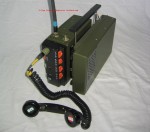 The M252 Pegasus
was a simplex or duplex, VHF mobile or
transportable radiotelephone designed by
Mobile Lab4 in the early 1970s, and based on
the M202 FM Olympic electronics modules.
It was designed to meet a specification from
the British Army Royal Signals for a
ruggedised VHF mobile primarily intended for
non-combat applications such as military
policing, home defence, etc. operating in the
VHF low band frequencies (66 - 88 MHz - Pye
'E' band). It was later (in 1981)
developed to operate in the 148-174 MHz and
132-156 MHz PMR radiotelephone
bands. It is pictured
here mounted in the man-portable battery
powered kit.
Where the standard M201/M202/M212 Olympic
used a die-cast aluminium frame to house a
single motherboard and multiple plug-in
daughter boards, the M252 used a cast
aluminium platform chassis which allowed for
double sided construction and two mother
boards. This gave space inside the set
for up to 18 channels of TX and RX crystal
oscillators, a twin-head receiver option and
various selective calling options.
See internal view of the main
radio section fitted with twin head
receiver modules and also a view of the
other side of the chassis where the 18
channel oscillator PCBs are
located, along with sockets for
internal selective calling units etc. The M252 Pegasus
was a simplex or duplex, VHF mobile or
transportable radiotelephone designed by
Mobile Lab4 in the early 1970s, and based on
the M202 FM Olympic electronics modules.
It was designed to meet a specification from
the British Army Royal Signals for a
ruggedised VHF mobile primarily intended for
non-combat applications such as military
policing, home defence, etc. operating in the
VHF low band frequencies (66 - 88 MHz - Pye
'E' band). It was later (in 1981)
developed to operate in the 148-174 MHz and
132-156 MHz PMR radiotelephone
bands. It is pictured
here mounted in the man-portable battery
powered kit.
Where the standard M201/M202/M212 Olympic
used a die-cast aluminium frame to house a
single motherboard and multiple plug-in
daughter boards, the M252 used a cast
aluminium platform chassis which allowed for
double sided construction and two mother
boards. This gave space inside the set
for up to 18 channels of TX and RX crystal
oscillators, a twin-head receiver option and
various selective calling options.
See internal view of the main
radio section fitted with twin head
receiver modules and also a view of the
other side of the chassis where the 18
channel oscillator PCBs are
located, along with sockets for
internal selective calling units etc.
The M252 was designed to be water resistant to
'Driving Rain' standard similar to the later
IEC/IP54 specification, and rugged enough for
use in a wide range of military vehicles,
motorcycles and helicopters. The
original design was extensively tested on the
MOD Blandford ranges strapped underneath a
Chieftain tank, but is not believed to have
ever been used in that particular
configuration in anger! The unit was
also successfully EMP tested.
The M252 Pegasus was a member of a large
family of mobiles, base stations and
accessories designed for use by the military,
and the mobile unit could be configured in
many different ways to suit the individual
contract. See the Pegasus system
product leaflet.
The mobile was a 12 Volt dc powered
equipment, and for use in 24 volt vehicles the
M200 Olympic VR200 voltage dropping unit was
available. The Pegasus mobile unit could
be vehicle mounted, or slotted into a battery
powered transportable fitted with a
nickel-cadmium battery pack. (This model
was later replaced by the FM914PM version of
the FM900 mobile) The chassis casting
had provision for two antenna sockets and a
version of the set was capable of duplex
operation, including talk-through.
After a very long testing period, the
British Army and RAF did use the M252, however
the Ministry of Defence (MOD) never bought
huge quantities of the M252 for the original
application, but did buy them later for the
nationwide UK Home Defence radio network
called "Mould" operated by the Army. It
is not thought that any of the dedicated
Pegasus F252 fixed stations were ever
purchased and there is no record of final
documentation being produced by the Company.
When the MOD failed to purchase the
expected large quantities of the M252, the
extensive development work on the design
(which included water proof castings,
interconnect cables and control heads) was
used to create various commercial versions of
the equipment. The commercial waterproof
version was called the Beaver (M254 local
control version, M256 remote control version),
and was finished in a yellow/black colour,
similar to that used for heavy earth-moving
plant and construction site equipment.
The non-waterproof commercial version was
called the M258 FM Olympic and was finished in
a blue/black color scheme.
A wide range of industry standard
selective calling facilities were available
for mounting internally in the radio unit,
including: 5 tone sequential (in-band audio
tones, referred to as 5-tone), continuous tone
coded squelch system (sub audio band tones,
referred to as CTCSS). External FFSK
selective calling encoder/decoder units for
the Mould system could also be connected via
the external facility socket. External
16 bit digital encryption units working to the
full Racal/Nato standard were also used for
some applications.
Production
life: 1976 - 1986
Standard
frequency range: 68 - 88 MHz, 148-174
MHz, 132-156 MHz
Transmitter
RF output: 5 - 15 Watts FM adjustable
Primary
model variants: simplex, duplex, twin
head, extended control/second operator control,
transportable version, motorcycle version, fixed
mobile version
Pegasus System product sales leaflet:
yes to follow
|
| Top of page |
|
Reporter
MF6AM (1976)
 A single product, low cost
VHF AM replacement for MF5AM mobile. The
MF6AM was designed by the Mobile Lab 3 (the AM
mobile Lab) , another of the small 'Boutique'
development labs which was re-located from
Newmarket Road to Banhams Marina, Cambridge and
led by Keith Fisher. It was primarily
intended for the UK market, at a time when the
Pye Telecom products were coming under price
pressure from competitors, both from smaller UK
companies and from Far-East imports.
Although low powered with few options, the
product was very successful in the UK AM home
market, and achieved all its business
objectives. A single product, low cost
VHF AM replacement for MF5AM mobile. The
MF6AM was designed by the Mobile Lab 3 (the AM
mobile Lab) , another of the small 'Boutique'
development labs which was re-located from
Newmarket Road to Banhams Marina, Cambridge and
led by Keith Fisher. It was primarily
intended for the UK market, at a time when the
Pye Telecom products were coming under price
pressure from competitors, both from smaller UK
companies and from Far-East imports.
Although low powered with few options, the
product was very successful in the UK AM home
market, and achieved all its business
objectives.
The design approach adopted was to eliminate as
many interconnect costs as was practicable and
to minimise the mechanical costs and complexity
where possible compared to the Olympic series
and Europa series. The product used an
extruded aluminium sleeve to provide a simple,
low-cost, but robust outer wrapper and an
combined aluminium rear panel and heat
sink. Internally three
printed circuit boards were mounted in a
simple steel chassis frame with the top PCB
hinged via a flexible wire strip. See
inside view with the top PCB hinged open.
In its most simple form the equipment could be
supplied with a combined microphone/loudspeaker
unit.
This was the first of the eighth generation
mobile products, and the success of the product
led to the design project to create the M290
crystal controlled series which is discussed
below.
To be continued
Production
life:
Standard
frequency range:
Transmitter RF
output:
Primary
model variants:
Product
sales leaflet: yes to follow
|
|
|
|
Hermes
Series HMS (1977)
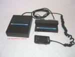 A family of low-power FM
mobiles based on a common TX/RX unit, intended
for sale in West Germany and those European
countries which had maximum TX power limits of
6 - 15 Watts. The equipment
was available for use as a mobile or as a base
station. The mobile
version used either a control head or a
combined microphone/hand controller, and the
base station version mounted the controls and
keypad on the unit case top cover. The
core transceiver was a 6 channel crystal
controlled unit. See view of mobile
unit with
top cover removed and also view
of PCB inside chassis. A family of low-power FM
mobiles based on a common TX/RX unit, intended
for sale in West Germany and those European
countries which had maximum TX power limits of
6 - 15 Watts. The equipment
was available for use as a mobile or as a base
station. The mobile
version used either a control head or a
combined microphone/hand controller, and the
base station version mounted the controls and
keypad on the unit case top cover. The
core transceiver was a 6 channel crystal
controlled unit. See view of mobile
unit with
top cover removed and also view
of PCB inside chassis.
In terms of technology platforms, this could
be considered to be eighth generation, and
similar technically to the Cambridge designed
M294/M296 series. Hermes
was designed by the Philips mobile radio
design lab at Hilversum, The Netherlands (who
had previously designed the Philips LTS
Lotus mobile and SXA/SNA Sexta portables
etc.) and was the last PMR product designed by
that group.
Individual prototype Hermes units from the
Netherlands were tested in the UK by Mobile
Lab4, and passed for pre-production.
However evaluation of units from the
pre-production run subsequently carried out at
the Cambridge Works factory indicated that the
equipment did not reliably meet its design
specifications and would have difficulty in
passing the tough German Type Approval
regulations. The project was cancelled
and the pre-production units scrapped.
The launch customer was intended to be the
Royal Navy for use on board ships.
Several of the pre-production units leaked out
of the Company and are now in the hands of
private collectors. The microphone/hand
controller was later used as an engineers
handset on the F490 series base stations.
Production life: Project cancelled
after pilot production run in Cambridge at the
Cambridge Works factory.
Standard
frequency
range: 148 - 174 and 450 - 470 MHz
Transmitter RF output: 6 Watts
Primary model variants:
HMS06 VHF, HMS16 UHF, mobile or fixed station,
local control, remote control and extended
control over a 100 metre multi-core cable.
Supporting
Products: none other than above items
Product
sales leaflet: No record
of a product leaflet being produced
Extract from technical
manual: No record of a manual being
produced
|
|
|
|
M206 Series
(1978)
 The M206 remote
mount mobile is often assumed to be just
another member of the M200 Olympic family due
to the use of a similar case construction by
the M203 AM Olympic. The M206 remote
mount mobile is often assumed to be just
another member of the M200 Olympic family due
to the use of a similar case construction by
the M203 AM Olympic.
However the
M206 was a specific development by Mobile
Lab 4 (the FM mobile Lab) for export to
markets of USA influence such as Canada,
Middle East and the Far East, and most of
the circuit design was new work. The M206
can be considered a successor to the PMR2FM.
In order to compete with Motorola
products such as the Micor and Mitrek, the
M206 had the highest performance receiver ever
produced by Pye Telecom, giving 100dB adjacent
channel selectivity and 80dB intermodulation
protection with good production margins. The
options available were simplex or duplex
operation, 4 or 16 channels, 10 Watt receiver
audio, twin head receiver, and an IF noise
blanker. So that both
simplex and duplex operation could be
achieved, the receiver and transmitter
circuits were arranged on opposite sides of
the steel platform chassis. See
M206 top
side view (transmitter section) and underside
view (receiver section).
The product was initially
designated the M206A, after the original FM
Olympic-based M204, M206, M214, M216 design
project was cancelled at the final model
stage, and priority switched
away from Olympic remote mount equipment and
the European CEPT duplex radiophone market to
the international high power export
market. The new
M206 product design utilised the mechanics and
heat sink designed for the original duplex
M204 and M214 equipments, and subsequently
used by the M203. (See the original UHF
M214 CEPT duplex twin-head design, module
side view and underside
view ). As the
large heat sink and case from the original
M206 had been dimensioned for a 25 Watt
continuous duplex radiophone, it was therefore
very suitable for PMR
applications at a 25 Watt
duplex and 50 Watt simplex 1:4 duty cycle.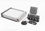
The small plastic remote control head designed
for the M203 was intended to be used with the
M206. However the Cairo Police, who were
the launch customer for the new M206A,
required a more rugged unit, and so a new
control box was created from the front panel
assembly of the M252 Pegasus, fitted with a
new rear casting. This later also became
the control unit for the remote mount FM
Olympic and Beaver range etc. See photo
of the Cairo Police duplex prototype at right.
Despite the high performance and
innovative circuit design, the crystal
controlled M206 would only be considered as
part of eighth generation technology.
However the M206X synthesised version
introduced the ninth generation mobile
synthesiser technology into the M206 range.
The writer took over as
Engineering Product Development Manager
(Design Team Leader) for the M206 project, and
can state the above information
with complete authority.
Production life: 1978 - 1982
Standard frequency range: A,
B, E, G, H bands, single RF head or twin RF head
receiver
Transmitter RF output: up to 50 Watts
adjustable Simplex, 25 Watts adjustable Duplex
Primary model variants: M206AA
duplex, M206X synthesised, the M206X was also
used as the basis for experimental 5KHz SSB
mobiles for a UK Home Office Project. A
double-decker M208 version with a 120 Watt
power amplifier was
planned but never produced.
Supporting
Products: Ruggedised control unit,
first used by Cairo Police, later used on the
Beaver, 10 watt loudspeaker unit with heat sink
voice coil, IF noise blanker (later used on some
base station products).
Product
sales leaflet: yes to follow
|
|
|
|
M290 Series
(1979 etc)
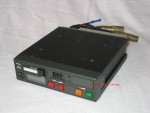 An eighth generation
technology platform of single PCB construction,
DIN sized, crystal controlled AM and FM dash
mounts, intended as lower cost equipment than
the Olympic M200 and Europa dash mount series.
Designed by the AM Mobile Lab at Banhams
Marina, Cambridge after the success of the
MF6AM. An eighth generation
technology platform of single PCB construction,
DIN sized, crystal controlled AM and FM dash
mounts, intended as lower cost equipment than
the Olympic M200 and Europa dash mount series.
Designed by the AM Mobile Lab at Banhams
Marina, Cambridge after the success of the
MF6AM.
The lead product in the family was the M294 VHF
FM model which was followed by the M296 UHF FM
equipment and the M293 VHF AM version. In
terms of volume sales this product family was
very successful and is believed to have been the
highest selling product ever produced by Pye
Telecom.
See internal
view of PCB top-side.
Production life:
Standard
frequency
range:
to follow
Transmitter RF
output: 10 - 25 Watts according to
model and power setting
Primary
model variants: M294E
(A band only), created as a test bed for surface
mount component assembly and then marketed as a
lower cost variant of the M294.
Product
sales leaflet: yes to follow
|
|
|
|
MX290
Series (1982-1984)
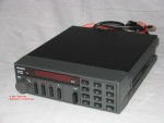 The MX290 series was Pye
Telecoms first volume production
synthesised mobile, and included AM, FM, VHF
and UHF equipment in dash mount format only.
It was often confused with the M290
crystal controlled series (designed by
Mobile Lab 3), due to the use of the same
front panel plastic mouldings on the basic 16
channel MX290 version and the same internal
signaling modules. The MX290 series was Pye
Telecoms first volume production
synthesised mobile, and included AM, FM, VHF
and UHF equipment in dash mount format only.
It was often confused with the M290
crystal controlled series (designed by
Mobile Lab 3), due to the use of the same
front panel plastic mouldings on the basic 16
channel MX290 version and the same internal
signaling modules.
However the lead product, the MX294, was a
separate development by a separate team
(Mobile Lab 4). Mechanically
it
used
a
new die cast frame, rear heat sink, lids and PCB,
and electrically was derived partly from the
M206 mobile, partly from the M206X Advanced
Development Project (which evaluated the
Mullard LOCMOS synthesiser integrated
circuits), and partly new circuit
design. A limited function remote mount
version was planned but not implemented.
The writer was the Engineering
Product Development Manager (Design Team
Leader) for the MX294 lead product in the
MX290 series, and can state
the above with complete authority.
The MX290 would be considered as
ninth generation technology along with the
M206X.
Photos to follow
To be continued
Production
life: 1982 - 1989
Standard
frequency range: A, AW,
B, E, T, U, K bands
Transmitter RF
output: 5 - 25 Watts adjustable,
Simplex
Primary model
variants: Cassette
mounting tray, 40/ 80
channels & keypad
versions using the systems front panel
assembly.
Product
sales
leaflet: yes to follow
|
|
|
|
M300 Project
(1983)
An AM/FM synthesised remote mount mobile,
submitted as a contender for a large UK Home
Office Police contract, but which lost to the
Marconi RC690 equipment.
In technology terms, the M300
spanned the seventh, eighth and ninth
generation, using as it did, circuit elements
from the M200, the M290, and the MX290 series.
To be continued
Production
life: cancelled after pre production
Standard
frequency
range:
A band and B band
Transmitter RF
output:
Primary
model variants: remote mount only
Product
sales
leaflet: no
record of sales leaflet being produced
|
|
|
|
UK
"Jerk & Run" Mobile Project (1983)
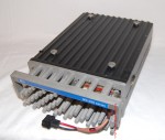 In technology terms, this
development from the same team as the M203 and
the M300, also spanned the seventh, eighth and
ninth generations, using circuit elements from
the M200, the M290, and the MX290 series.
See internal
top side view and underside
view. In technology terms, this
development from the same team as the M203 and
the M300, also spanned the seventh, eighth and
ninth generations, using circuit elements from
the M200, the M290, and the MX290 series.
See internal
top side view and underside
view.
The project was cancelled and the
pre-production units scrapped. The launch
customer was intended to be the UK Home
Office. Several of the pre-production
equipments units (which for convenience had used
the front panels parts and logo strips from the
MX290 series) leaked out of the Company and are
now in the hands of private collectors.
This gave rise to the erroneous belief that
there were remote mount MX290 equipments
produced.
More to follow
Production
life: cancelled after pre-production
Standard
frequency range:
Transmitter RF
output:
Primary
model variants: remote mount only
Product
sales
leaflet: no record of sales leaflet
being produced
Extract
from technical manual: no record of
manual being produced
|
|
|
|
FM900 Series
(1983)
 An advanced family of
microprocessor controlled, remote control and
local control mobiles. This was
conceived and developed by the design team at
Philips Communications, Clayton, Melbourne,
Australia, and was possibly the worlds first
fully microprocessor controlled PMR
mobile. It was certainly the worlds most
advanced PMR mobile radio at the time. An advanced family of
microprocessor controlled, remote control and
local control mobiles. This was
conceived and developed by the design team at
Philips Communications, Clayton, Melbourne,
Australia, and was possibly the worlds first
fully microprocessor controlled PMR
mobile. It was certainly the worlds most
advanced PMR mobile radio at the time.
The family initially consisted of the FM91
remote mount, which could be simplex or
continuous duplex, and the FM92 local
controlled version. This was later
followed by the FM93, a lower cost and
re-styled version of the FM92.
Other specialist versions included a
public correspondence radiophone version sold
as the BT Sapphire, and the FM914PM military
equipment to replace the M252 Pegasus used by
the British Army, shown below right. The
FM914PM used external
selective calling encoder/decoder units for
the Mould system connected via an external
facility socket. External 16 bit digital
encryption units working to the full
GCHQ/Racal standard were also used for some
applications.
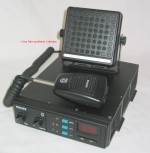 The FM900 mobile was first
produced in Australia, later in the UK and
Spain, with application specific design
derivatives produced in France by TRT for use
on the Ramage Police network. The FM900 mobile was first
produced in Australia, later in the UK and
Spain, with application specific design
derivatives produced in France by TRT for use
on the Ramage Police network. 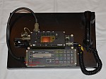 Tenth generation technology platform.
Production
life:
Standard
frequency range:
Transmitter RF
output:
Primary
model variants:
Product sales leaflet: yes to follow
for some versions
|
|
|
|
284M/286M Series
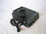 This was a series of VHF
and UHF dash mount mobiles designed and
manufactured by Marantz in Japan and sold by
Philips companies to non-European non-CEPT
specification markets around the world during
the 1980s.
The initial equipment design was a 4
channel crystal controlled circuit, with a
transmitter RF output of up to 40 Watts on VHF
and 35 Watts on UHF. Later equipments
used a frequency synthesiser with diode-matrix
programming to set the TX and RX
frequencies. See
top view of UHF model 286M.
NV Philips owned 49% of the Marantz
shares, but the radio communications division
of Marantz was fiercely independent, and
normally marketed its products under the
"Standard" brand name through its own agents
and dealers. Marantz also worked in
close association with Standard Radio of the
USA, who funded some of the product
designs. During the 1980s several
serious attempts were made by Philips
European PMR companies to
engage in joint activities with Marantz,
however little was achieved; the very top
management of Marantz preferring the Company
to remain independent. The writer spent
some time in Japan as part of one of these
joint projects. The 284M/286M product branded
with the Philips name is one of the few
results of these liaison attempts. This was a series of VHF
and UHF dash mount mobiles designed and
manufactured by Marantz in Japan and sold by
Philips companies to non-European non-CEPT
specification markets around the world during
the 1980s.
The initial equipment design was a 4
channel crystal controlled circuit, with a
transmitter RF output of up to 40 Watts on VHF
and 35 Watts on UHF. Later equipments
used a frequency synthesiser with diode-matrix
programming to set the TX and RX
frequencies. See
top view of UHF model 286M.
NV Philips owned 49% of the Marantz
shares, but the radio communications division
of Marantz was fiercely independent, and
normally marketed its products under the
"Standard" brand name through its own agents
and dealers. Marantz also worked in
close association with Standard Radio of the
USA, who funded some of the product
designs. During the 1980s several
serious attempts were made by Philips
European PMR companies to
engage in joint activities with Marantz,
however little was achieved; the very top
management of Marantz preferring the Company
to remain independent. The writer spent
some time in Japan as part of one of these
joint projects. The 284M/286M product branded
with the Philips name is one of the few
results of these liaison attempts.
Production
life: Mid-late 1980s
Standard
frequency range: VHF 138 - 144, 144 -
150, 150 - 157, 156 - 163, 162 - 169, 168 - 174
MHz, UHF 406 - 420, 450 - 470, 470 - 490, 490 -
512 MHz
Transmitter RF
output: VHF 10, 25, 40 W versions, UHF
10, 25, 35 W versions
Primary
model variants: Dash mount
simplex only, CTCSS option
Product
sales
leaflet: yes to follow
|
| Top of page |
|
CM42/CM87/NCM
Project
(1980)
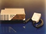
This
group of concept studies and advanced
development programs are listed because of
their significance to subsequent products such
as the FM1000 series.
In the early 1980s the Philips Mobile
Radio Management Group (MRMG) initiated a
series of market and product concept studies
which were intended to lead to the design of
the architecture and component parts for a
universal, world-wide, Philips "Concern
Mobile" and other products. The
programs were also intended to eliminate rival
& duplicate development projects from the
various Pye & Philips design teams around
the world, following the internal political
and economic competition which took place
within the organisation during the late 1970s.
CM42/CM87
The Concern Mobile 42 and Concern Mobile
87 projects were joint marketing and
engineering concept studies begun in 1980 to
identify the mobile radio requirements of the
main Philips National Sales Organizations
(NSO) around the world, and to create a
universal product concept which would
successfully meet those market requirements.
The market requirements and broad band
circuit design technology of CM42/87 were
later used in the FM1000 mobile when it became
clear that the NCM semiconductor technology
would not be available until the end of the
decade.
NCM
The New Concern Mobile Project (NCM) was
an advanced development
program intended to create a
family of custom silicon integrated circuits
from which mobiles, portables, fixed
stations and radio pagers could be
constructed. The resulting semiconductor
design technology was never actually used in
PMR mobiles and portables, and the PMR work
was canceled at the advanced
development stage following the first wafer
diffusion. However
some semiconductor technology work
continued and the result was
used in the PG32 POCSAG pager family and later
series of Philips pagers.
Production
life: design study only
Standard
frequency range: VHF, UHF
Transmitter RF
output: 30W
Primary
model variants: dash mount and
remote mount
Product
sales
leaflet: none produced
Extract
from technical manual: none produced,
technical reports and models only
|
|
|
|
FM710
& FM715 Mobiles (1988)
A pair of VHF and
UHF FM synthesised dash-mount mobiles designed and
manufactured by EF Johnson of Minneapolis,
USA and sold by
Philips National Sales Organisations (NSO) to
countries which based their type approval
specifications for radio
equipment on the USA EIA
and MIL standards rather than the European
CEPT specifications.
The FM710 was a UHF 30 Watt 99 channel mobile
and the FM715was a VHF 40 Watt 99 channel
mobile.
Product sales
leaflet: yes to follow
|
| Top of page |
|
730MX (1986)
 A synthesised dash mount
mobile designed by Philips in Wadeville, South
Africa and based around
the Mullard synthesiser integrated circuits. A synthesised dash mount
mobile designed by Philips in Wadeville, South
Africa and based around
the Mullard synthesiser integrated circuits.
Development of the 730MX was started by Gert
Sijbesma in 1984, however during 1987, following
the formation of the Philips RCS Business Unit,
production of the 730MX ceased in favour of
other mobile products to be supplied from the
various International Product Supply Centres
within PRCS. Production of the SXA, SNA
and Eland continued in South Africa as did
specialised integrated circuits for use in the
SXA and SNA by India and Brazil.
|
| Top of page |
|
FM1000
Series (1989 etc)
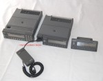 A
major mid-market/upper-market FM mobile series
developed out of the CM42/CM87/NCM marketing
and engineering studies of the early
1980s. The series was based on a core
transceiver unit which could be utilised as a
local control or remote controlled
station. Three different control
consoles were available; the LCD keypad and
display unit, the LCD numeric display unit,
and the standard unit which used led
indicators only. A
major mid-market/upper-market FM mobile series
developed out of the CM42/CM87/NCM marketing
and engineering studies of the early
1980s. The series was based on a core
transceiver unit which could be utilised as a
local control or remote controlled
station. Three different control
consoles were available; the LCD keypad and
display unit, the LCD numeric display unit,
and the standard unit which used led
indicators only.
The market requirements and
broadband circuit design concepts of NCM and
CM42/87 were used in the FM1000 mobile when it
became clear that the NCM semiconductor
technology would not be available until the
end of the decade and that a discrete
component based product family was required in
the interim to replace the MX290 series and
FM900 series.
The analogue signaling version was termed
FM1100. The MPT1327/1343 trunking version was
termed FM1200. The version for use with
the Philips TN100 proprietary
trunking system was the
FM1300. A version was also configured
for use with the Mobitex data system, this was
termed FM1400. A small number of FM1100
were configured to work with the DCU900 data
signalling control head, originally intended
for the FM900.
Eleventh generation technology platform
on the basis of the wide bandwidth RF design
and extensive microprocessor control.
FM1000 was the first all-processor controlled
radio designed by the Cambridge International
Product Supply Centre (IPSC).
Production
life: 1989 - 1998
Standard
frequency range:
Transmitter RF
output: 1-30 Watts adjustable,
according to frequency band
Primary
model variants: FM1100,
FM1200, FM1300, FM1400, plus supporting range of
ancillaries
Product
sales
leaflet(s): Yes, several versions of
the brochure to follow, including the first
draft leaflet which was rejected and all but 10
copies destroyed
|
|
|
|
PRM80
Series (1989 etc)
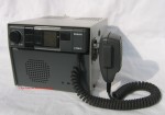 This product was specified
by PRCS Corporate Headquarters in the UK as an
international low-cost mobile project and was
developed by the design team at Philips
Communications, Clayton, Melbourne, Australia,
who had previously designed the FM900 series. This product was specified
by PRCS Corporate Headquarters in the UK as an
international low-cost mobile project and was
developed by the design team at Philips
Communications, Clayton, Melbourne, Australia,
who had previously designed the FM900 series.
The PRM80 was originally conceived as small 25
Watt synthesised FM dash mount mobile with two
model versions; a 9 channel unit and a 40
channel unit. The design was
subsequently expanded by the Australian design
team to include a remote mount version and a
keypad/alpha-numeric display version.
Both analogue signaling and trunk signaling
versions are still in service when this was
written in 2007.
The PRM80 was initially called the FM420
project by the Australian design team and
later given the type designation PRM80 in
order to fit into the Philips corporate
product numbering scheme. First
produced in Australia in 1989, later in the UK
and India.
It should be noted that following the
retrenchment of NV Philips from many of the
professional business sectors from 1990
onwards and the return of the Philips PMR
companies to local control (as opposed to
central control), some versions of the PMR80
family designed in the UK and Australia were
given the same type numbers, despite having
different hardware, firmware and
software.
The PRM80 won design awards in Australia
and The
Netherlands.
Technology platform status twelfth
generation
Production
life: 1989 - 1998
Standard
frequency range:
Transmitter RF
output:
Primary
model variants:
Product
sales
leaflet: yes to follow
|
|
|
|
SRM82
(Raywood DSP Mobile) (1998)
The SRM82 was a dedicated data
communications mobile designed by the Raywood
company for use with taxi system data control
units (prior to the purchase of the company by
Simoco in 1996).
Technology platform status thirteenth generation
Photos to follow
Production
life:
Standard
frequency range:
Transmitter RF
output:
Primary
model variants:
Product
sales
leaflet: yes to follow
|
|
|
|
SRM1000
Tetra mobile
First generation Tetra digital PMR mobile
designed in Cambridge and first used on the UK
commercial Dolphin network (now closed down).
Technology platform status
fourteenth overall.
Photos to follow
To be continued
Production
life:
Standard
frequency range:
Transmitter RF
output:
Primary
model variants:
Product
sales
leaflet: to follow
|
|
|
|
SRM9000 DSP
mobile
A replacement for the PRM80 family
developed from the Raywood DSP technology by the
Australian design centre.
To be continued
Production
life: Current production
Standard
frequency range:
Transmitter RF
output:
Primary
model variants:
Product
sales
leaflet: Yes, when I can find it.
|
|
|
|
|
|