|
|
|
Military Wireless, Radar & Navigation
Equipment 1939
- 1966
|
|
Major equipments where Pye was involved in all or part
of the
original
design
|
|
|
|
In addition to the
above, Pye Ltd manufactured
many other equipment designs
for the Government during WW2.
Also, original designs of Pye
Ltd such as WS18, WS19, WS22,
PCR, RF Amplifier No.2
were manufactured by other
companies in the UK and
overseas to increase
production quantities.
WS62 was also manufactured in
Australia and India by Pye
associated companies.
|
|
|
Please
note: The chronological
order is approximate
|
|
|
Radar Systems (1939 - 1946)
Air Interception Radar (AI)
(part
involvement in 200MHz
versions)
Chain Home Low Radar
(part involvement)
Air-Surface Vessel Radar
(ASV) (part
involvement in 200 MHz
versions)
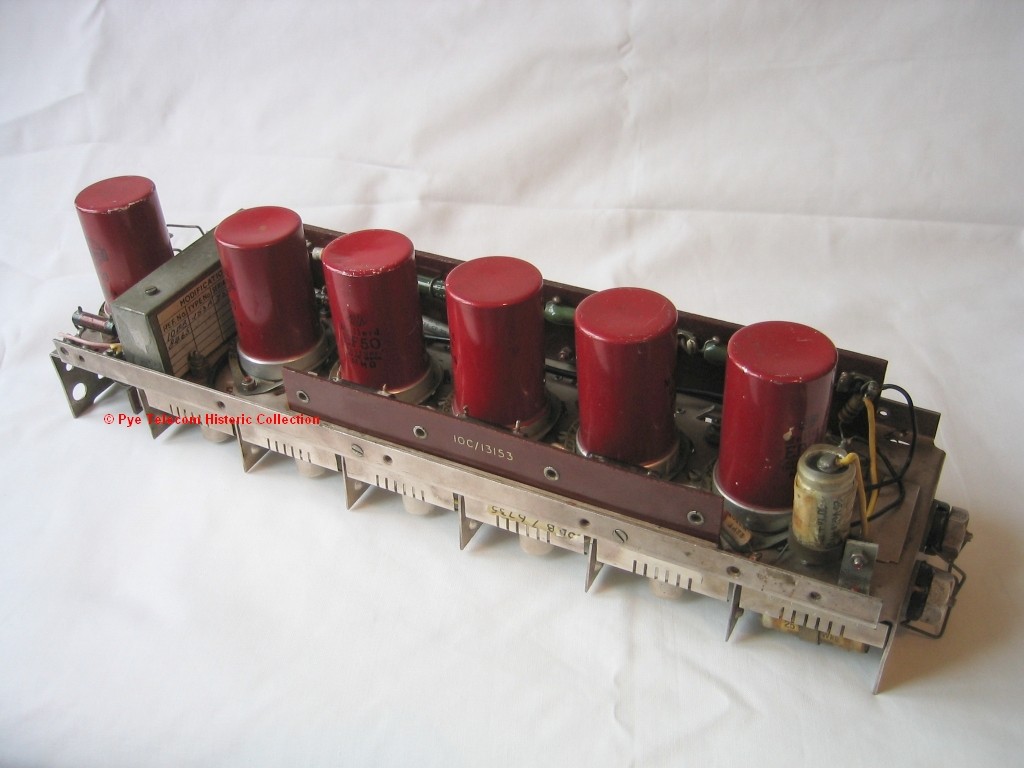
 From
1939 onwards, Pye Ltd made
an important contribution to
the early airborne radar
receivers by supplying
amplifying units based on an
existing 45 MHz TRF
television chassis which
used the revolutionary new
Philips/Mullard EF50 valve
designed by NV Philips in
Eindhoven. From
1939 onwards, Pye Ltd made
an important contribution to
the early airborne radar
receivers by supplying
amplifying units based on an
existing 45 MHz TRF
television chassis which
used the revolutionary new
Philips/Mullard EF50 valve
designed by NV Philips in
Eindhoven.
Work
by
the
Government
on
airborne
radar had started well
before Britain joined the
second world war and
followed the design of the
ground based Chain Home
system. Pye had
designed a high gain TRF
television receiver to
receive the prewar London TV
station which broadcast on
45MHz. This was based
on the Philips EF50 valve
supplied by Mullard, the
Philips UK subsidiary.
The Pye 45MHz TV receiver
circuit was found to be an
excellent basis for the
Intermediate Frequency (IF)
amplifier and detector
stages of Airborne
Interception radar
receivers, due to the gain,
bandwidth and selectivity
characteristics. Pye
and Ekco supplied the early
radar receivers before Ekco
and AC Cossor became the
main suppliers and Pye
concentrated on land warfare
equipment such as WS18,
WS19, WS22 etc.
According
to
the
memoirs of E.G. Bowen, Pye
supplied over 12,000 of the
200 MHz radar receiver
units and indicator units
for the 200 MHz radar
systems AI MKI, AI MKII, AI
MKIII, AI MKIV and ASV MKI,
ASV MKII and ASV MKIII.
Time
scales: 1939 - 1945
Standard frequency
range: Radar receivers
Type R3039, R3041 etc. 176 -
200 MHz, Receiving Unit Type
153 45MHz ± 2MHz
Transmitter RF output:
N/A
Primary
model variants:
Various AI and ASV receivers
(see
http:/home.btconnect.com/gmb/ari.htm)
Receiving Unit Type 153A
(10DB/8465) or the circuit
configuration was built into
other equipment platforms
Extract from technical
manual: manual
not
produced by Pye
|
|
|
|
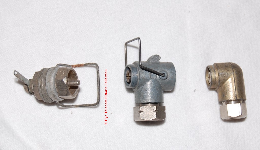
Pye
Co-axial
Connector (1939)
 An
important
innovation from this time was
the "Pye plug" coaxial
connector, conceived for
the early AI and ASV radar
equipments by
Donald (Bo) Jackson and
designed by mechanical
designer George Baguley.
The objective was to provide
quickly detachable coaxial
cables between the modules of
the early airborne radar
equipment and avoid the
problem of poor high-frequency
impedance matching (poor
return loss and reflected
signals) in cables which would
otherwise have been terminated
in a simple 'pig-tail'
soldered connection. An
important
innovation from this time was
the "Pye plug" coaxial
connector, conceived for
the early AI and ASV radar
equipments by
Donald (Bo) Jackson and
designed by mechanical
designer George Baguley.
The objective was to provide
quickly detachable coaxial
cables between the modules of
the early airborne radar
equipment and avoid the
problem of poor high-frequency
impedance matching (poor
return loss and reflected
signals) in cables which would
otherwise have been terminated
in a simple 'pig-tail'
soldered connection.
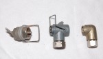
The initial Pye connector was
a right-angle elbow type with
a range of different size
co-ax cable entry clamps, but
was expanded to include
straight , T-piece and
back-to-back connectors.
The design was subsequently
used in the majority of
British RF equipment during
the war. Illustrated
above left are the Pye plug
and socket and T-piece.
The connector design was also
used by Pye Telecom
commercially on all of the
radio-telephone equipment from
1946 until the end of the
Ranger series of mobiles and
base stations in 1964.
Pye
Connector in use from 1939 to
1969 in Military service
|
| Top
of page |
|
|
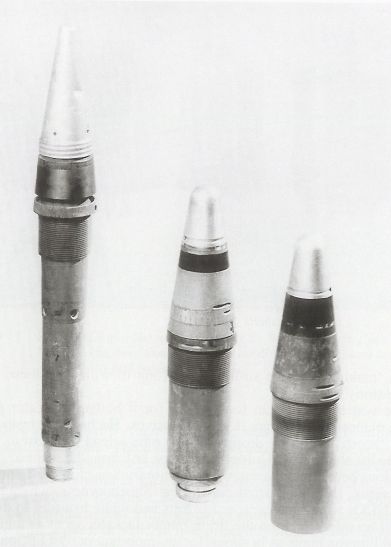
Anti-Aircraft Radio
Proximity Fuze (1939 -
1942) (conceptual
and
prototype design work)
 Between
September 1939 and 1942, at
the request of Sir John
Cockroft of the Ministry of
Supply, the radar team at
Pye Ltd carried our
pioneering experimental work
on radio proximity fuzes for
anti-aircraft artillery
shells. This work
included the design,
in-house manufacture and
testing of suitable
miniature thermionic
valves. Between
September 1939 and 1942, at
the request of Sir John
Cockroft of the Ministry of
Supply, the radar team at
Pye Ltd carried our
pioneering experimental work
on radio proximity fuzes for
anti-aircraft artillery
shells. This work
included the design,
in-house manufacture and
testing of suitable
miniature thermionic
valves.
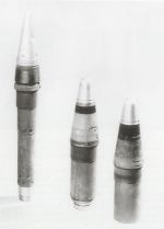
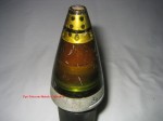
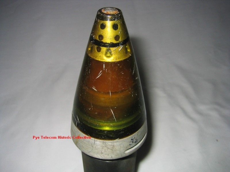
The
proximity fuze was a
miniature radio transmitter
and receiver/detector fitted
in the nose of an
anti-aircraft shell, which
detonated when close to the
aircraft. This
required components which
could withstand the shock of
the shell being fired from
the gun.
Later,
in September 1940, details
of the early work on
proximity fuzes were handed
over to the USA by the
Tizard Mission,
along with the secrets of
the Magnetron Radar valve
and the Jet engine.
Development and
production the proximity
fuze concept was finally
achieved by the Americans
near the end of the
war. See image of USA
MK45 radio proximity fuze
below right. This
operated at approx 225 MHz.
Time Scales:
1939 - 1942
Standard frequency
range: TBA
Transmitter RF
output: TBA
Primary model
variants: TBA
Extract
from
technical manual:
Technical details
not in PTL Historic Collection
|
|
|
|
|
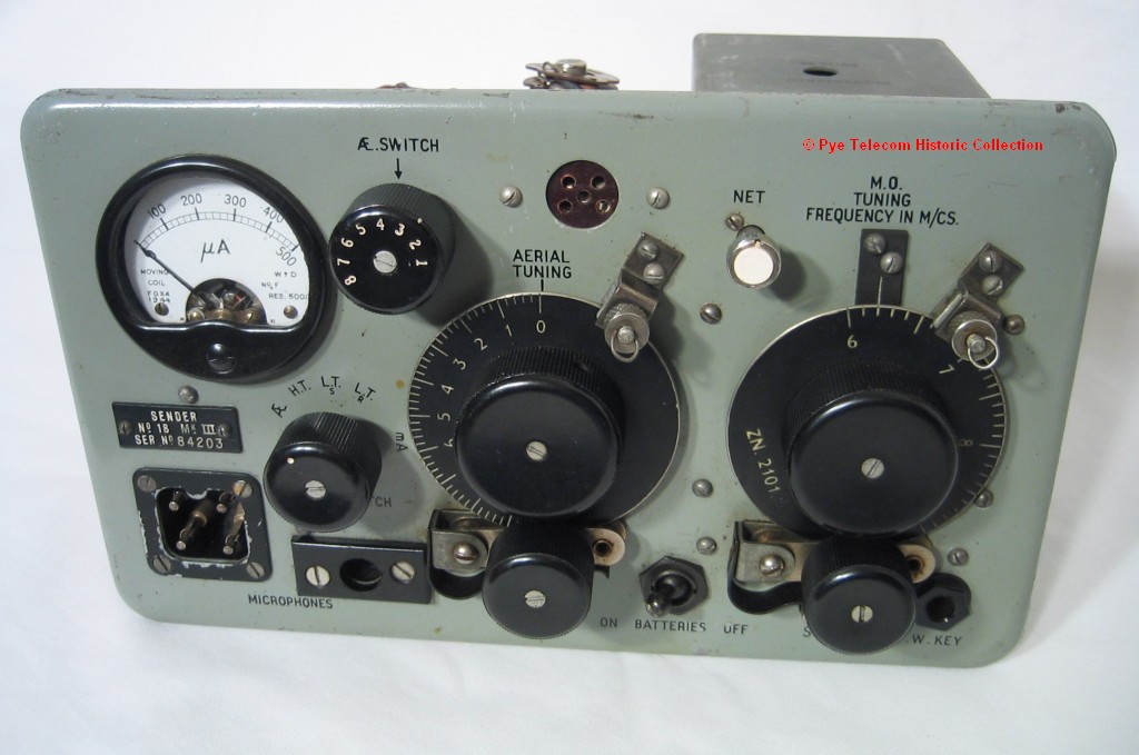
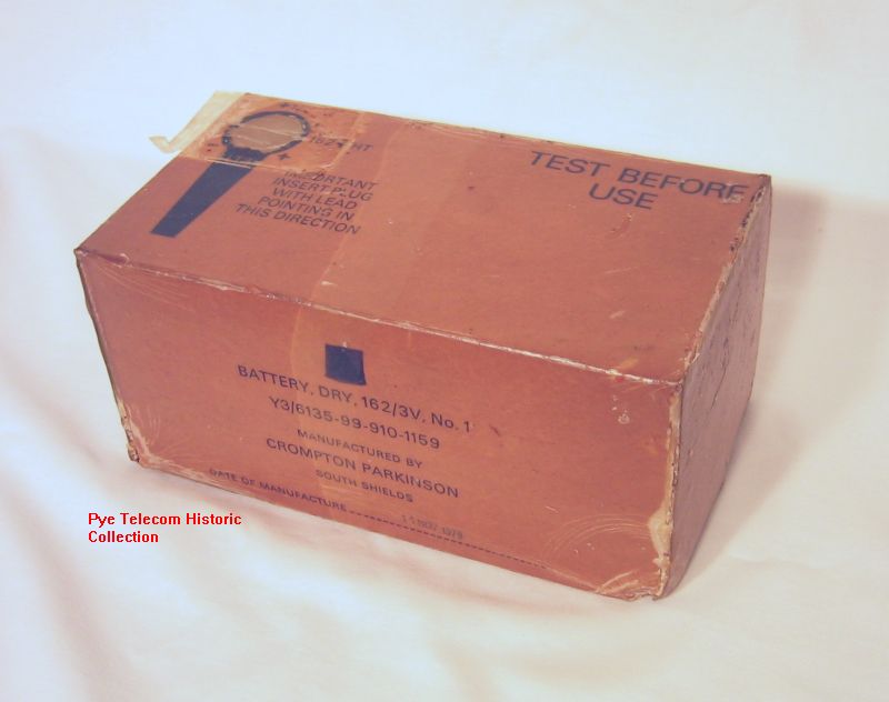
Wireless Set No. 18 (1940)
 Wireless
Set
No. 18 was the first volume
production man-pack radio
station for the British
Infantry. It was based
on a design by the
Government Signals
Experimental Establishment
(SEE). Wireless
Set
No. 18 was the first volume
production man-pack radio
station for the British
Infantry. It was based
on a design by the
Government Signals
Experimental Establishment
(SEE).
In 1939 Pye Ltd was asked to
quote for the production of
the SEE design, but
declined, claiming it was
not suitable for the purpose
intended on the grounds of
weight and
construction. Within 6
weeks Pye produced samples
of two alternative equipment
configurations which were
then sent to France for
field-trial. Pye
requested that the sets
should be made from
aluminium but this was not
permitted due to material
shortages and the Company
was directed to use sheet
steel as with the SEE
prototypes. To reduce
weight Pye then turned to
thin tin-plate for the case,
which was strengthened by
deeply pressed
ribbing. This
light-weight case design
with characteristic deep
ribbing became the standard
for many of the WW2 Pye
designed equipments (WS19,
WS22, WS62, PCR, WS R10, WS
Sound Ranging MK2 etc).
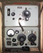
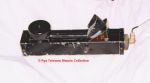
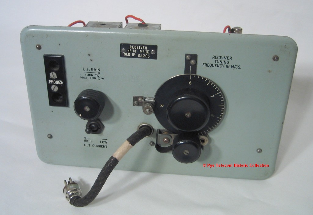
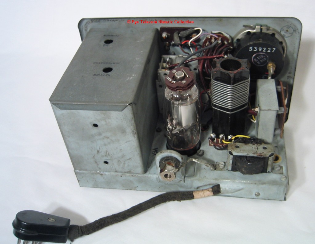
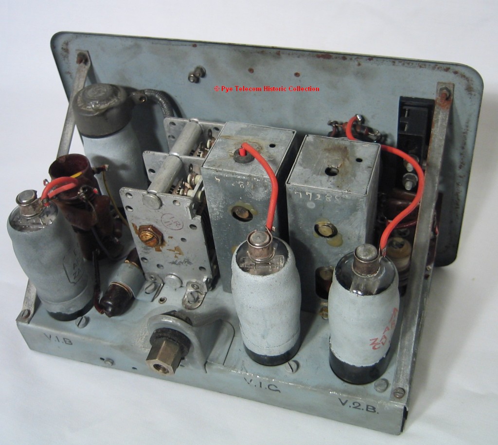
The WS18 equipment
consists of separate
tuneable transmitter
and receiver
modules mounted in a
back-pack style carrying
case, complete with integral
battery mounted in the
base of the case. A
sectional vertical rod
aerial was used mounted on a
base at the side of the
case. Alternatively a
long wire ground aerial
could be used to make the
operator and station less
conspicuous. A pair of
metal flaps and folding
canvas hood provided water
protection to the front of
the unit. The
equipment was designed to be
carried by one man and
operated by a second.
The valves used were
relatively fragile 2 Volt
filament types. These
sometimes limited the
operational use of the
equipment when (according to
Pye Ltd employees who
conducted post-events
analysis on equipments
returned from the field) the
internal valve filament
support springs fractured
during parachute drops, as
in Operation Market Garden
near Arnhem. See internal
view of transmitter
and internal
view of receiver.
The
particular
WS18
equipment illustrated above
was manufactured by Invicta
Radio, another company
operated by the Stanley
family, owners of the Pye
Group at the time.
Production life:
1939 - 1945
Standard frequency
range: 6 - 9 MHz
Transmitter RF
output:
0.25 Watt
Primary model
variants: Wireless
Sets No 68R, WS68T, WS68P
covering lower frequency
ranges
Extract
from technical manual:
Yes, to follow
|
|
|
|
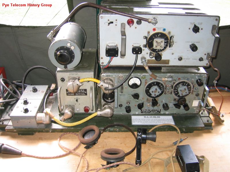
Wireless Sets No.19 (1941)
 The
world famous Wireless Sets No.
19 was a system of local and
extended control vehicular
mobile radio units which were
originally designed to provide
medium range HF communications
and local intercom facilities
(WS19 specification), plus
short range VHF communications
(WS24 specification), for the
crew of British Army armoured
fighting vehicles (AFV). The
world famous Wireless Sets No.
19 was a system of local and
extended control vehicular
mobile radio units which were
originally designed to provide
medium range HF communications
and local intercom facilities
(WS19 specification), plus
short range VHF communications
(WS24 specification), for the
crew of British Army armoured
fighting vehicles (AFV).
Although the specifications
for WS19/24 were created in
the late 1930s, WS19 appears
to have been developed by Pye
Ltd in a great hurry late in
1940 after the British
Expeditionary Force (BEF)
experienced combat against the
German forces and their
fast-moving and coordinated
mobile warfare in
France. The methodology
of the German Army involved
integrated armoured and
infantry divisions with their
movements co-ordinated by
radio communications.
This military concept was
subsequently given the title
of lightning warfare or
Blitzkreig by the British.
Following
its introduction in British
AFV in 1941, and despite its
weight, the WS19 equipment was
found to be so significantly
useful and versatile as to be
used in a very wide variety of
vehicles, ground and airborne
applications. In order
to increase the volume of
production the design was soon
manufactured by a number of
other companies in the UK,
Canada and USA. The
Canadian MKIII model was the
most technically refined
version. Some USA
produced MKII equipment were
made with dual English/Russian
legend. Royal Signals
figures show that a total of
115,000 units were made during
WWII. The
equipment (with various
modifications) was also
adopted by the Canadian,
Australian and Italian Armies
as their standard HF vehicle
mobile radio unit.
The installation of each WS19
was customised to the
particular vehicle type or
application by a specific
installation kit, however
every complete WS19 station
consisted of a number of
standard parts including the
transceiver unit, a power
supply unit, an aerial
variometer unit, two antenna
bases and rod assemblies, a
number of crew control units,
each with headsets (and
microphones for some crew
members) an equipment carrier
and extensive cable harnesses.
WS19
was an original design created
by Pye Ltd in Cambridge,
England in three months of
concentrated work in 1940 and
over the period of the war
years evolved through three
different primary model
versions and a number of
secondary variants, re
manufactured and modified
models. It remained in
service with the British Army
until the late 1960s.
From
1955 onwards the equipment was
partly replaced in armoured
fighting vehicles applications
by the Pye Wireless Set C12,
due to delays in the
introduction of the planned
replacement equipment
Wireless Set C13. The
total
active service life of the
WS19 equipment series with the
British Army was from 1941 to
the late 1960s.
For an extremely detailed and
authoritative account of WS19
see Louis Meulstee, Wireless
For the Warrior Volume 2,
1998, originally published by
G. C. Arnold & Partners,
ISBN 1898805 10 5, now
published by Wimborne
Publishing. The web site
for Louis Meulstee is:
http://wftw.nl/
Other
images will follow when there
is time to assemble a complete
station for photography.
Production life:
1941 - 1946 (Pye Ltd)
Many sets manufactured and
re-manufactured by other
companies and Government
departments
Service Life:
1941 - 1963
Standard frequency
range: A set MKI
2.5-6.25 MHz, MKII and MKIII 2
- 8 MHz, B set 229 - 241
MHz
Transmitter RF
output: CW 3 - 5
Watts or greater, AM 1.5 - 2.5
Watts or greater (Note there
are wide variations in the RF
output between sets)
Primary model
variants: British
versions - MKI,
MKII,MKII*, MKII,
MKIII/T, MKIII Reconditioned
Post-War, Canadian Versions -
MKII, MKIII
USA Versions - MKII,
Australian Versions - MKII
Extract from
technical manual:
Yes, to follow
Detailed product
history: See WS19 history file for more
details
|
|
|
|
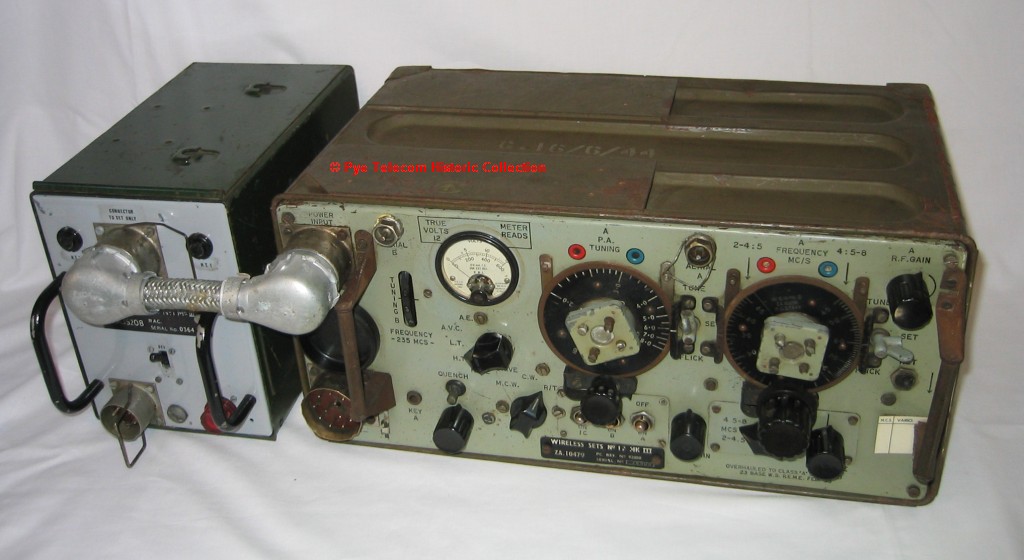
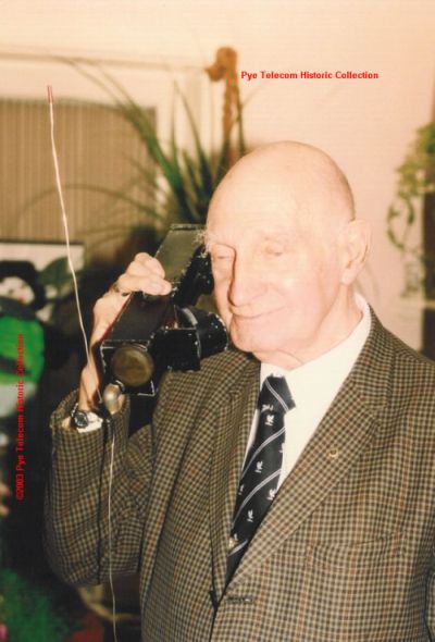
Infantry Handset
Radiotelephone (1942)
 This small VHF hand held
radio using miniature
wire-ended valves was
designed by Pye Ltd in 1942
to allow Infantry Soldiers
to communicate with Tank
Crews who already used the
230 MHz "B" set of Wireless
Sets No.19 for tank to tank
communication. It was
intended to have a similar
range to that of the tank
WS19 "B" set and to fulfill
the reciprocal requirement
of the specification for
Wireless Set No. 24, in
other words for the Infantry
to be able to talk back to
the tank "B" set. Its
use was formally proposed in
a secret report by Pye
Ltd to the Ministry of
Supply in 1942.
This small VHF hand held
radio using miniature
wire-ended valves was
designed by Pye Ltd in 1942
to allow Infantry Soldiers
to communicate with Tank
Crews who already used the
230 MHz "B" set of Wireless
Sets No.19 for tank to tank
communication. It was
intended to have a similar
range to that of the tank
WS19 "B" set and to fulfill
the reciprocal requirement
of the specification for
Wireless Set No. 24, in
other words for the Infantry
to be able to talk back to
the tank "B" set. Its
use was formally proposed in
a secret report by Pye
Ltd to the Ministry of
Supply in 1942.
However,
the
Ministry preferred to make
use of an
extra Wireless Set No. 38
mounted in the AFV to talk
directly to the other WS38
equipments already in use by
the Infantry Soldiers.
Eventually a special
version of WS38 (WS38AFV)
was configured to integrate
with the WS19 control
harness system mounted in
vehicles.
It
is believed that early in
the war, samples of the Pye
VHF hand-held set were
supplied to the USA and
Canada.
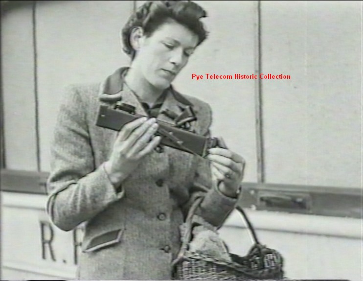
After the War, the
equipment
was featured in a short film
demonstrating the future use
of personal radio
communications by the
general public. See
image at right below.
One of the designers
is pictured here posing with
the equipment in 1996. 
Time
Scales: 1942 -
1946
Standard
frequency range: 230 -
250 MHz
Transmitter RF output:
30mW
Receiver:
super-regenerative
Primary
model variants: One
version only
Extract
from technical manual:
No manual produced, Pye Ltd
report by Denis Fuller dated 9
November 1942 |
|
|
|
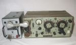
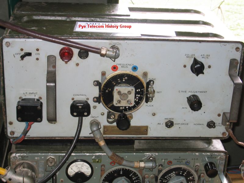
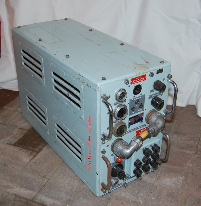
RF
Amplifier No. 2 (1942)
 RF
Amplifier No. 2 was an
external HF RF amplifier,
used to increase the
modulated transmitter output
power from the"A" Set
of Wireless Sets
No.19. Depending on
the frequency in use, the
equipment model and the
input drive power, output
powers between 15 and 35
Watts could be obtained. RF
Amplifier No. 2 was an
external HF RF amplifier,
used to increase the
modulated transmitter output
power from the"A" Set
of Wireless Sets
No.19. Depending on
the frequency in use, the
equipment model and the
input drive power, output
powers between 15 and 35
Watts could be obtained.
MKI and MKII models
used four 807 valves in
parallel but the later MKIII
version used only two 807s
and a different bias
arrangement in order to
improve efficiency. A
large internal rotary
generator was used to
provide the 600 Volt HT
supply, and from the MKII
version onwards a fan on the
generator also circulated
cooling air into and out of
the case via a filter
mounted on the case back
panel. The complete
amplifier consumed an
additional 16 Amps at 12
Volts.
The RF Amplifier was
usually mounted
on top of the WS19,
and for antenna matching
used either its own special
tuning unit, or the Aerial
Tuning Unit Type J from
Wireless Set No. 22.
Post-war, a 24 Volt
version of the RF Amplifier
was manufactured by Burndept
Ltd. See image at
right.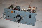
Production life:
12 Volt versions 1942 - 1946
Standard
frequency range: 2.1
- 7.5 MHz
Transmitter RF
output: 15 - 35 Watts
Primary
model variants: 12
Volt versions MK1, MKII,
MKIII, 24 Volt version of
MKIII only
Extract
from technical manual:
yes, to follow
|
|
|
|
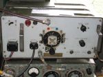
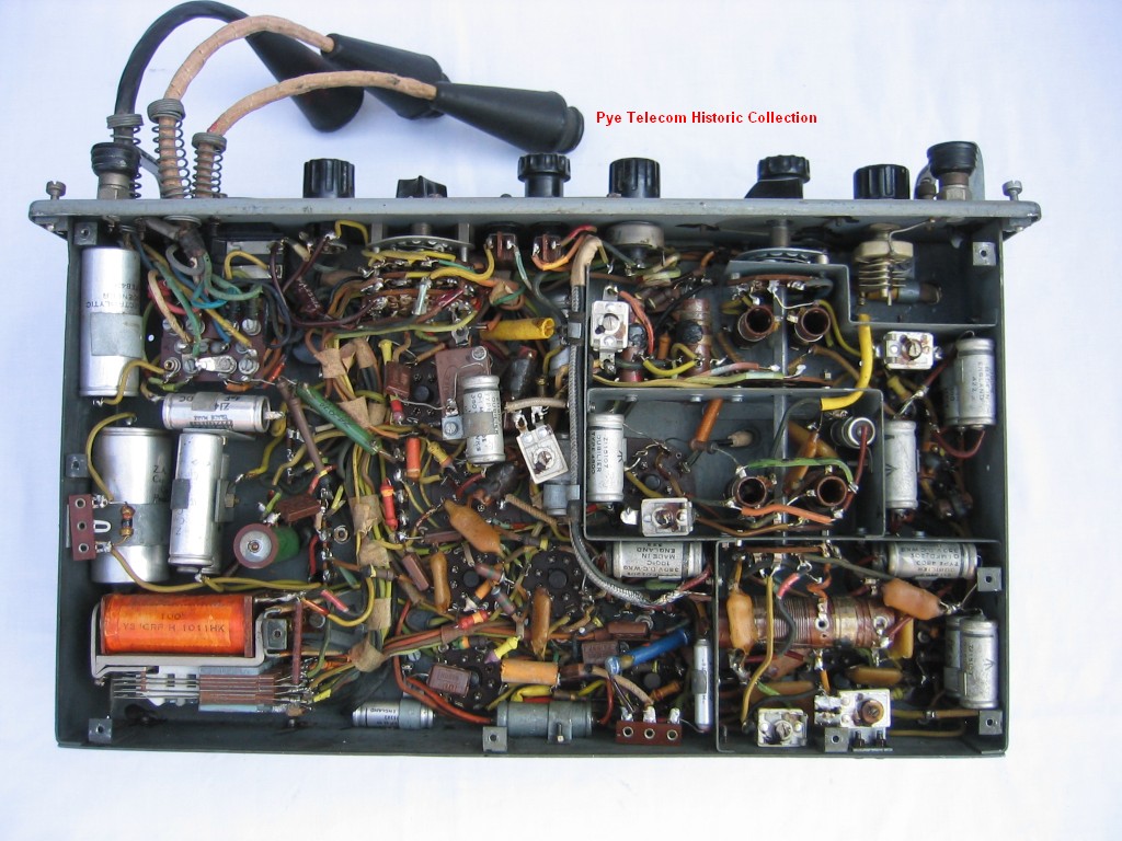
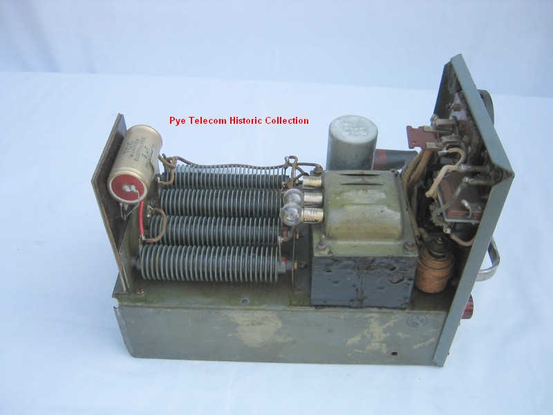
Wireless Sets No. 22 (1942)
 Wireless
Sets No. 22 was a general
purpose low powered HF
transmitter receiver
intended for use by the British
Army in
non-armoured vehicles.
It could also be configured
as a 3-man-pack load or for
animal-pack use, and was
also used on a transportable
hand cart. It had a similar
frequency range to WS19 and
was intended to provide a
similar performance,
although the transmit power
was lower. Wireless
Sets No. 22 was a general
purpose low powered HF
transmitter receiver
intended for use by the British
Army in
non-armoured vehicles.
It could also be configured
as a 3-man-pack load or for
animal-pack use, and was
also used on a transportable
hand cart. It had a similar
frequency range to WS19 and
was intended to provide a
similar performance,
although the transmit power
was lower.
The
internal layout was similar
to WS19 (although
the circuits were quite
different) except
that WS22 has an internal
roller-coaster aerial tuner
mounted where the WS19 had
the VHF "B" set and intercom
amplifier. See
internal
top side view and underside view. The front
panel layout of WS22 was
very similar to the original
prototype WS19 MKI.
WS
22 uses an external vibrator
power supply to generate
about 300 Volts dc from a 12
Volt battery source. See internal view of PSU.
Royal
signals records show that a
total of 55,000 units were
manufactured by Pye Ltd
and the Mitcham Works
factory of Philips Lamps.
For
certain applications
requiring either moisture
proofing or airborne
operation, WS22 was replaced
by Wireless Set No. 62,
(which was originally
designated WS22 MK2)
although the British army
continued to use WS22 for
general purpose low power
mobile applications until
the end of the 1950s.
More
to follow.
Production
life:
Standard
frequency range:
Transmitter RF output:
Primary
model variants:
Extract
from technical manual:
Yes,
to follow
Detailed product history:
to follow
|
|
|
|
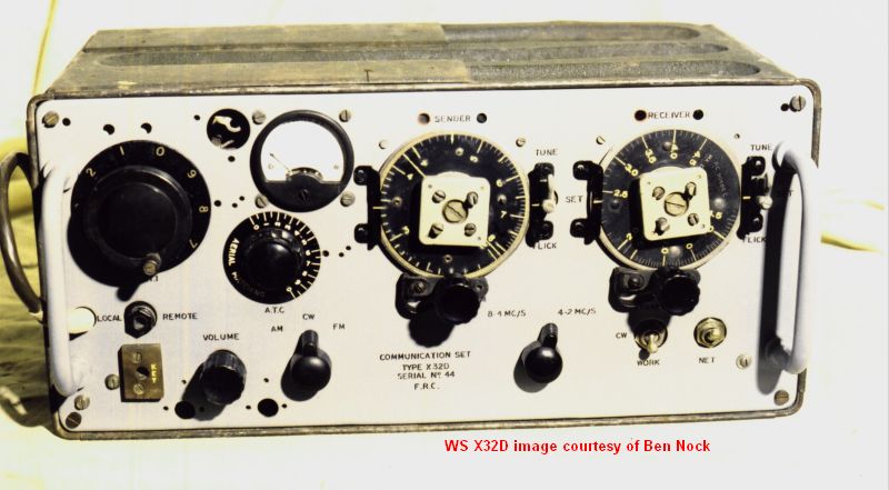
| Wireless Set No. X32D (1944)
 WS
X32
was a series of experimental
radios used by the British
Army to evaluate frequency
modulation (FM) in the HF
bands against the existing
amplitude modulation (AM)
method used during World War
II. WS
X32
was a series of experimental
radios used by the British
Army to evaluate frequency
modulation (FM) in the HF
bands against the existing
amplitude modulation (AM)
method used during World War
II.
The
USA pioneered FM in the late
1930s and much of the US
forces short range land
warfare communications used
this mode from the beginning
of their involvement in
World War 2.
Trial
WS
X32 equipments were designed
and manufactured by both Pye
and Murphy.
The Pye equipments WS X32D
were very similar in
external appearance to WS22,
as can be seen from the
above photograph kindly
supplied by Ben Nock.
More
to follow.
Production life:
Standard
frequency range:
Transmitter RF
output:
Primary
model variants:
Extract
from technical manual:
Manual
not
in PTL Historic Collection
|
|
|
|
Wireless
Set No 68
 A lower
frequency version of
Wireless Set No.18, covering
1.75 - 2.9 MHz or 3 - 5.2
MHz. A lower
frequency version of
Wireless Set No.18, covering
1.75 - 2.9 MHz or 3 - 5.2
MHz.
The
equipment was
introduced in 1943 in order
to permit longer range
communications by using
lower frequencies than used
by the standard WS18.
More
to follow.
Production life:
Standard
frequency range: WS68R
and WS68T: 3
- 5.2 MHz, WS68P:
1.75
- 2.9 MHz
Transmitter RF
output: 0.25W
Primary
model variants: WS68P,
WS68R, WS68T
Extract
from technical manual:Yes
to follow
|
|
|
|
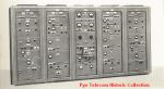
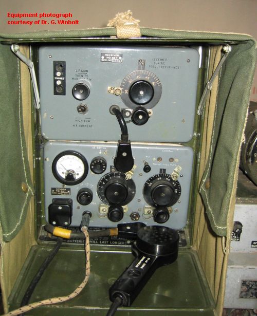
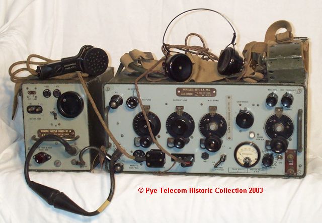
Radio Link Sound Ranging
MKII (1943)
The
Out-Station
 Radio
Link Sound Ranging MKII was
part of a system for capturing
the sounds of the firing of
enemy guns, and returning the
audio to a central station by
wireless means, so that the
range and location of the guns
could be determined.
Sound ranging was one of the
three techniques employed by
the British Army to locate
enemy guns, along with
Surveying and Flash Spotting. Radio
Link Sound Ranging MKII was
part of a system for capturing
the sounds of the firing of
enemy guns, and returning the
audio to a central station by
wireless means, so that the
range and location of the guns
could be determined.
Sound ranging was one of the
three techniques employed by
the British Army to locate
enemy guns, along with
Surveying and Flash Spotting.
The radio system consisted of
two types of HF
transmitter/receiver stations;
Wireless Sets Sound Ranging
Headquarters Station (WS
SR HQ) and Wireless Sets Sound
Ranging Out-Station (WS SR
OS), each of them man-pack
transportable.
A Sound Ranging troop
typically consisted of 8
stations, 7 WS SR OS and one
WS SR HQ. Up to 5 of the
Out-Stations would be deployed
in a row several thousand
yards apart, and would signal
the sound of enemy guns being
fired back to the Headquarters
Station on a narrow band of
frequencies around 10
MHz. Two additional
spotting stations were also
equipped with the Out-Station
wireless set for voice
reporting.
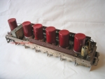
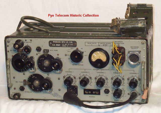
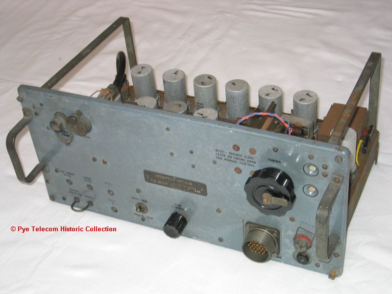
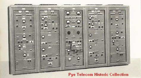
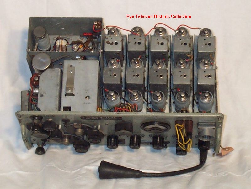
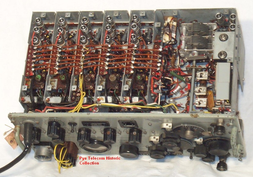
The Headquarters Station
 The
Headquarters
Station was unusual in that it
received the signal from the 5
Out-Stations simultaneously
and processed the signals
through 5 separate IF
amplifiers.
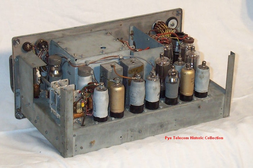
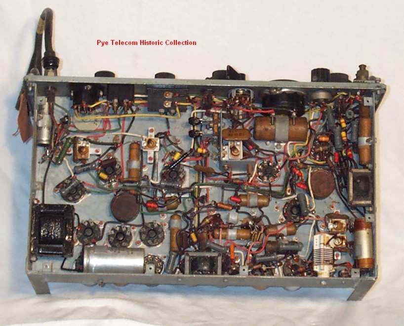
See
inside top view and underside view of HQ station and inside
top view and underside
view of Out-Station.
A
system of pen recording on
film rolls was used to create
a visual trace resulting from
the audio on the received
signals. The recorders
were produced by the Cambridge
Instrument Company. The
Headquarters
Station was unusual in that it
received the signal from the 5
Out-Stations simultaneously
and processed the signals
through 5 separate IF
amplifiers.
See
inside top view and underside view of HQ station and inside
top view and underside
view of Out-Station.
A
system of pen recording on
film rolls was used to create
a visual trace resulting from
the audio on the received
signals. The recorders
were produced by the Cambridge
Instrument Company.
The circuit design technology
used in both equipments was
derived from the Wireless Set
No. 18, and the
equipment
was
mounted
in
the
case
from
WS22.
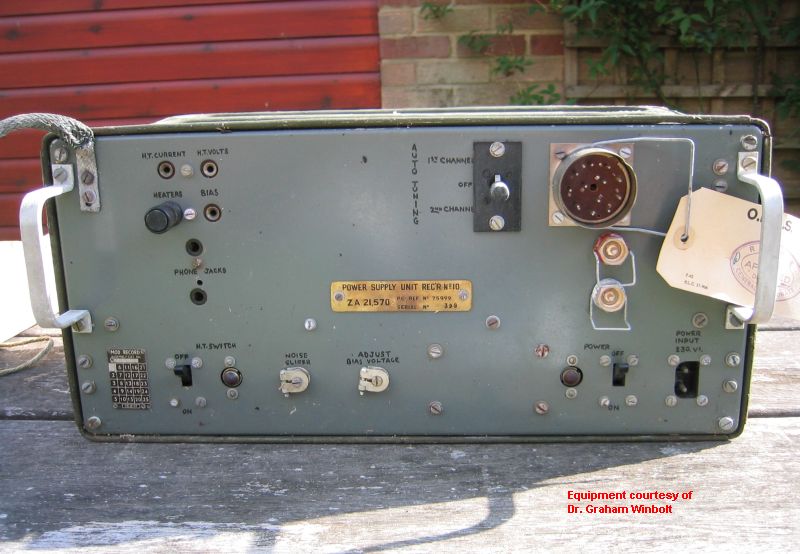
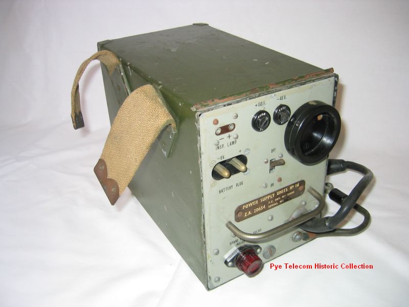
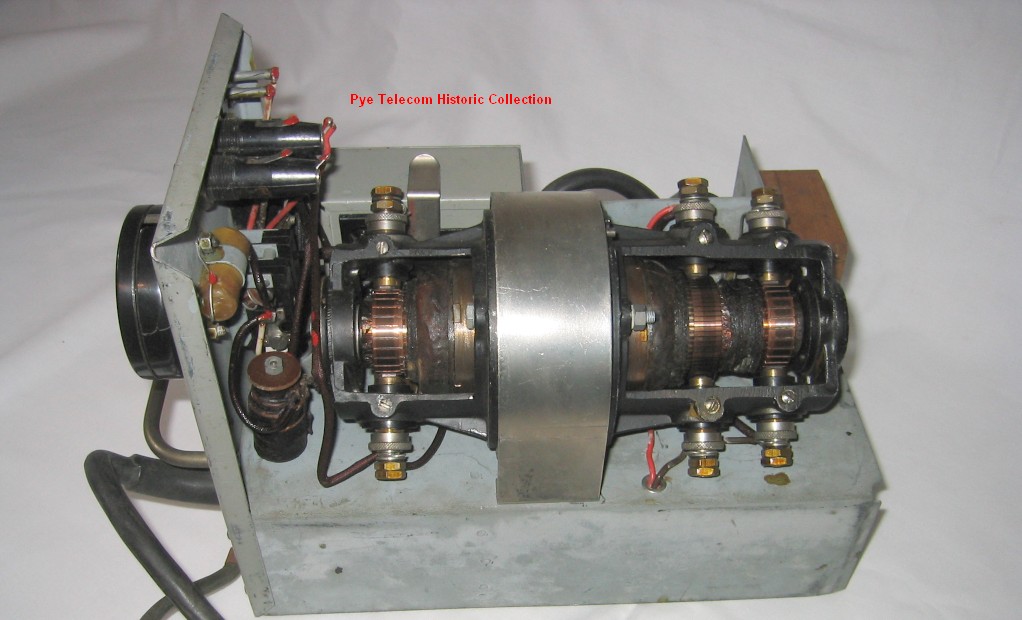
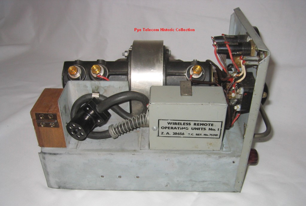
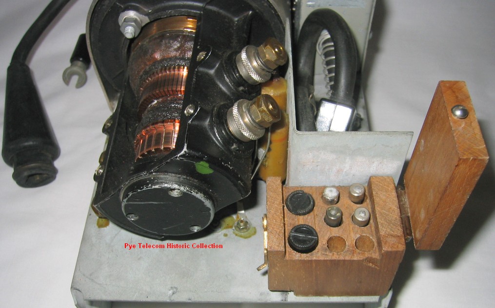
Separate
rotary
transformer Power
Supply
Units
No. 16 were used for
each station,
running from a 6 volt
battery. The rotary
transformer in the PSU
provided 150 Volt HT and 40
Volt bias supplies. See
inside view of the PSU showing
the rotary
transformer and also the
remote
control unit mounted
inside each PSU. Note
also the small
wooden box carrying
fuses and generator brushes,
the concept of which was
subsequently used in the mains
power supply for the PCR
receiver.
Production
life: 1943 - 1945
Standard
frequency range: 9 -
10.5 MHz in one range
Transmitter RF
output: 0.25 W
Primary
model variants: HQ
Station, Out-Station, PSU No
16, Unit Loud speaking, Film
Recorder SR.
Extract
from technical manual:
Yes, to follow
|
|
|
|
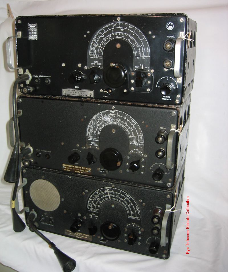
Portable
Communications Receiver Type
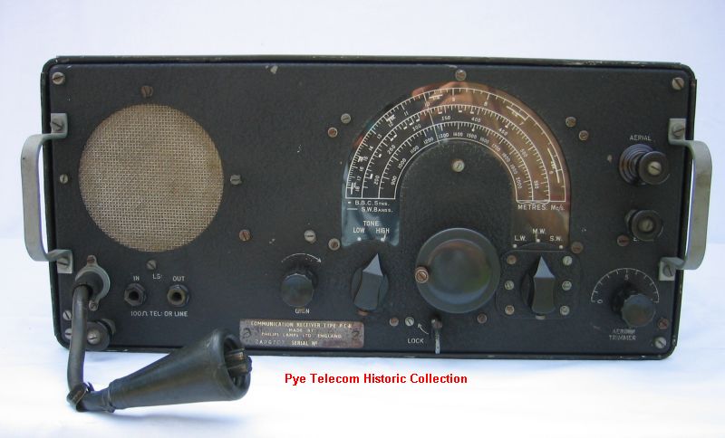
PCR, PCR1, PCR2, PCR3 (1944)
 Portable
Communications
Receiver
Type
PCR
was
the
first
model
in
a
series of general purpose
lightweight communications
receivers used by the
British Army world-wide from
mid 1944 until some time
during the late 1960s. Other
models are the PCR1, 2, 3,
and PCR3TPL. Portable
Communications
Receiver
Type
PCR
was
the
first
model
in
a
series of general purpose
lightweight communications
receivers used by the
British Army world-wide from
mid 1944 until some time
during the late 1960s. Other
models are the PCR1, 2, 3,
and PCR3TPL.
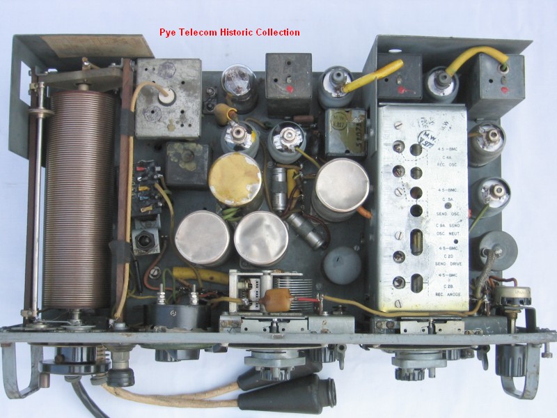
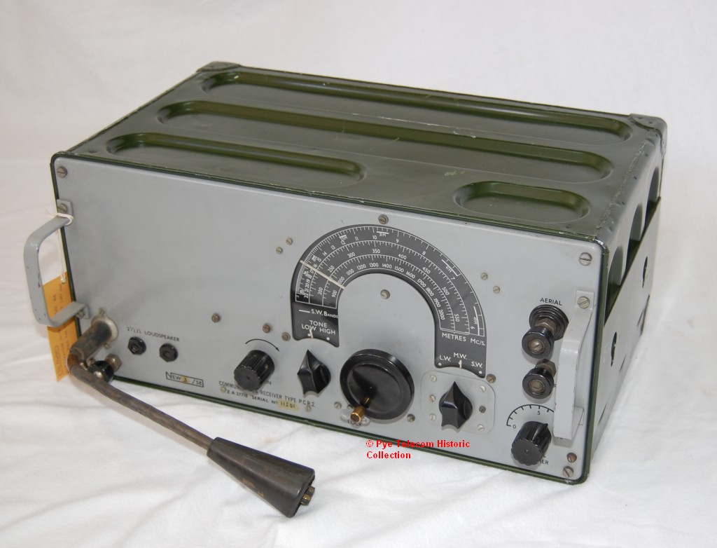
The PCR
receiver was a 6 valve
superhet, and electrically
was a variation of the
receiver section of the Pye
Wireless Sets No. 19, but
with the addition of some RF
input selectivity, slightly
narrower IF selectivity and
a higher power audio output
stage, using a 6V6 or EL32
valve according to
model. Bill Pannell is
thought to have been the
engineer responsible for the
equipment design, and Donald
H. Hughes, one of the senior
designers of WS18 and WS19,
has has been identified as
the engineering design
authority for the PCR
receiver, and his signature
appeared on the original
drawings.
The frequencies
covered by the initial PCR
model were 2100-850 Metres,
570-190 Metres and 5.8-18MHz
and the equipment had an
internal electro-magnetic
loudspeaker. Later
models covered slightly
different frequencies, used
an external loudspeaker and
had slightly different audio
input/output
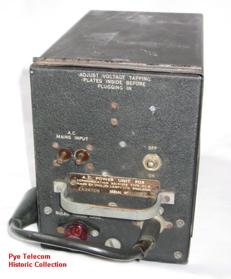
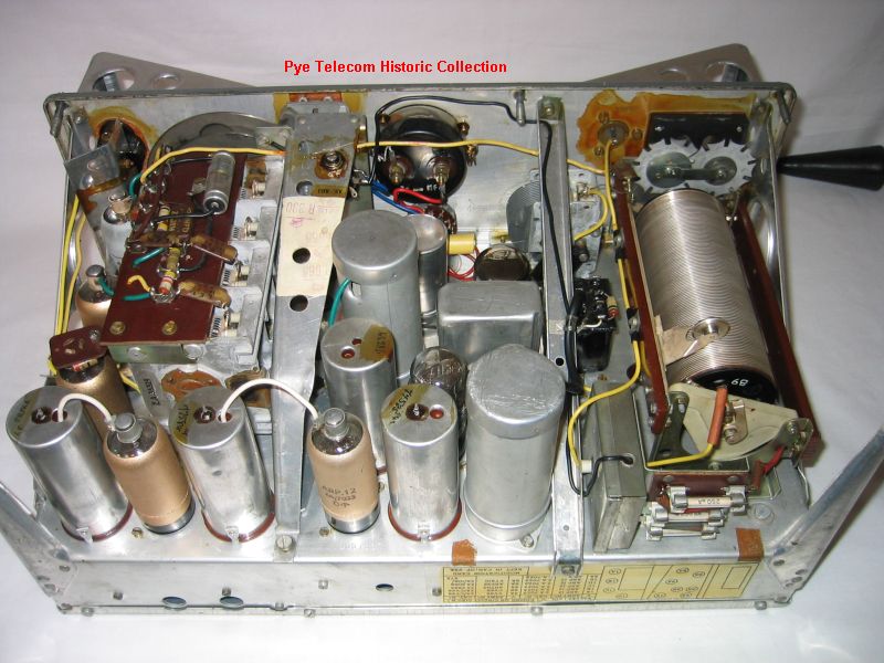
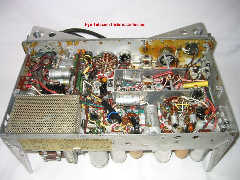
facilities. The PCR
series were all externally
powered from a separate mains PSU or a 12 Volt DC
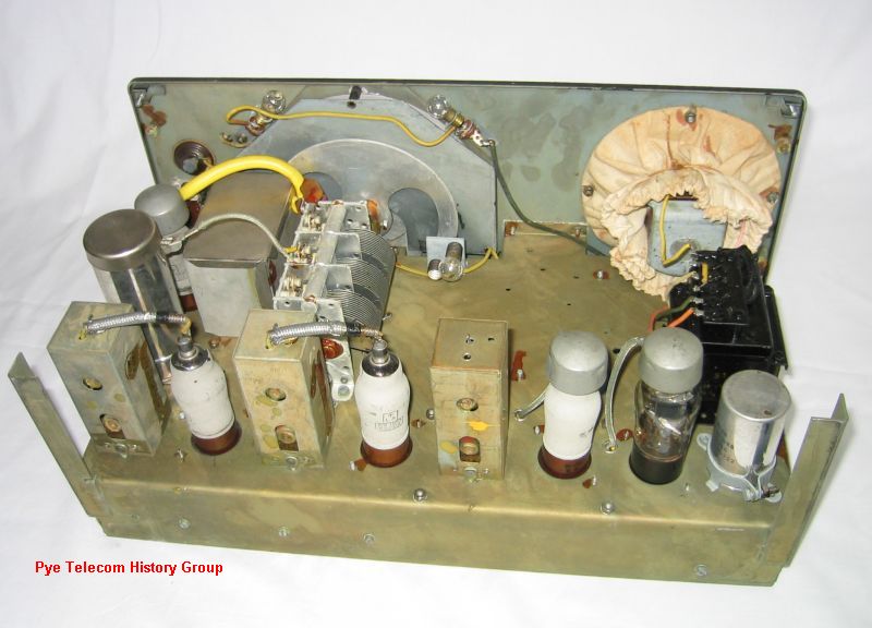
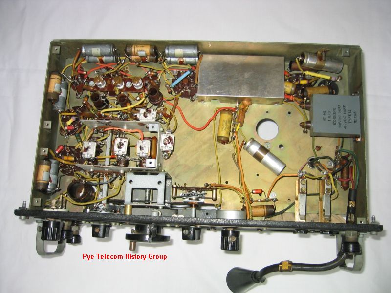
vibrator unit. See
inside top
view and underside
view.
The equipment front panel
was usually finished in
black wrinkle paint and the
set mounted in a gloss black
painted variant of the WS19
case. Due to the
inclusion of the standard
WS19 mounting slots in the
case sides, the set could be
carried in the WS19 carriers
(Carrier Sets No. 21,
23, 25). Versions of
the equipment have also been
found finished with a grey
panel and olive green case
and some coated with
tropicallised varnish.
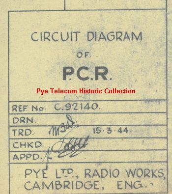
The equipment was designed
by Pye Ltd in Cambridge and
the drawings
finalised in March
1944. The design was
subsequently manufactured by
Pye, Philips Lamps and
Invicta Radio (another
company run by the Stanley
family who owned Pye Ltd).
Pye Ltd was initially
contracted to produce a
quantity of 5000 PCR1 and
12000 PCR2/3 units at a rate
of about 800 per
month. The total
Philips production figures
are not known, but from
serial numbers seen on
equipments, were likely to
have been been around 15,000
- 17,000 units. The
Pye equipments were
manufactured on an out-work
basis by teams of assemblers
in the "Pye Village
Industries" scheme in
village halls and other
buildings around East
Anglia. Once a week
the sets would be collected
by a man in a van
called Fred and taken to
Cambridge for testing and
despatch. The last PCR
equipments manufactured
by
Pye Ltd in
Cambridge were completed in
December 1945, and at the
end of production a few
extra sets were found to
have been made. These
were sold to employees for
£10 each. PCR
equipment manufactured by
Philips Lamps were produced
at their Mitcham Works
factory, South London, and
internally have the
inspection stamp marks "MW".
The PCR is often described
as a forces welfare receiver
or NAAFI receiver, however
this is thought to be a
popular myth, and most
certainly relates to a later post-war
application for
some of the large quantities
of sets remaining after the
war.
War-time
employees of Pye Ltd are
quite certain that the
equipment was intended as an
"Invasion
Receiver",
that is, a general purpose,
portable communications
receiver (hence the type
designation PCR) , for use
in Europe by the British 2nd
Army after the D-Day
Normandy landings, to
receive military progress
and information broadcasts
as part of Operation
Overlord, as the
various divisions moved
across Europe. The
term "Broadcast"
has a different meaning in
the Military, compared to
domestic radio
communications, and this may
have given rise to the
popular myth that the design
was originally intended for
the reception of domestic
broadcast signals.
Recent information from
British Armed Service
personnel indicates that the
set was also supplied by the
RAF to Resistance Groups in
Norway, Holland and
France. This is
confirmed by the Dutch
Royal Corps of Signals
Verbindingsdienst
web site. It was also
later used by the British
Army during the Korean war,
as was Wireless Sets No. 62.
Production life:
PYE Ltd - April
1944 - December 1945.
REME - Some
equipments re-built by the
REME Newark Depot
1958-1960 and carry the
legend
NEW 3 \
58 etc. to signify the
location, month and year
of re-manufacture.
Re-manufacture
- Some equipment
re-manufactured by other
contractors eg. WRNW
1958
Standard
frequency range:
PCR
&
PCR1 - 2100-850 Metres,
570-190 Metres and
5.8-18MHz
PCR2 - 2100-850
Metres, 570-190 Metres and
6.0-22MHz
PCR3 & PCR3TPL -
570-190 Metres,
2.3-7.3MHz, and 7.0-23MHz.
Transmitter RF
output: N/a,
receiver only
Primary model
variants: PCR,
PCR1, PCR2, PCR3, PCR3TPL,
also see Receiver Type PTR
below.
Extract from
technical manual:
Only the circuit diagram
and some sections of the
EMER are held in the
collection
|
|
|
|
Communications
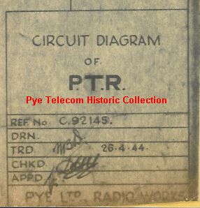
Receiver Type PTR (1944)
 A communications receiver
similar to the original
PCR receiver, which was
fitted with a BFO valve
stage and other circuit
features making it
suitable for both speech
and CW (Morse code)
reception.
The
quantity of PTR receivers
manufactured is not known.
Production
life:
Drawings issued in April
1944, no information on
production dates or
quantities.
Standard
frequency range:
Assumed to be the same as
the original PCR and PCR1
Transmitter RF
output: N/a,
receiver only
Primary model
variants: Not
known
Extract from
technical manual:
Circuit diagram only held
in the collection
A communications receiver
similar to the original
PCR receiver, which was
fitted with a BFO valve
stage and other circuit
features making it
suitable for both speech
and CW (Morse code)
reception.
The
quantity of PTR receivers
manufactured is not known.
Production
life:
Drawings issued in April
1944, no information on
production dates or
quantities.
Standard
frequency range:
Assumed to be the same as
the original PCR and PCR1
Transmitter RF
output: N/a,
receiver only
Primary model
variants: Not
known
Extract from
technical manual:
Circuit diagram only held
in the collection
|
|
|
|
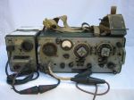
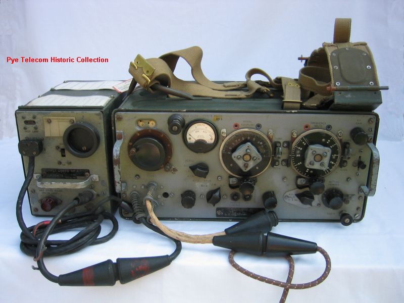
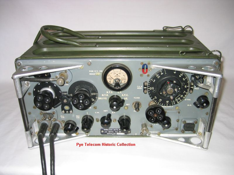
| Wireless Sets No. 62 (1945)
 Wireless
Sets No. 62 was a low
power, short range,
vehicle station HF
transmitter &
receiver. The
frequency range was 1.6 to
10.0 MHz in two
bands. It
was intended as an
interim, but lighter
and water proof
replacement, for Wireless
Set No. 22 MKI, which had
been in service with the
British Army since 1942,
and which was due to be
replaced by Wireless Set
No. 42. However the
WS42 project was abandoned
and WS62 became a
permanent equipment.
It was used by the British
and Australian Armies, and
possibly by the Canadians. Wireless
Sets No. 62 was a low
power, short range,
vehicle station HF
transmitter &
receiver. The
frequency range was 1.6 to
10.0 MHz in two
bands. It
was intended as an
interim, but lighter
and water proof
replacement, for Wireless
Set No. 22 MKI, which had
been in service with the
British Army since 1942,
and which was due to be
replaced by Wireless Set
No. 42. However the
WS42 project was abandoned
and WS62 became a
permanent equipment.
It was used by the British
and Australian Armies, and
possibly by the Canadians.
Designed
and produced only by Pye
Ltd in Cambridge, WS62 had
a long service life, being
first trialled early in
1944, with War-time
production running from
late 1944 to 1946, and
later production running
from 1952 until 1966 in
the UK. It was also
manufactured in Australia
and India.
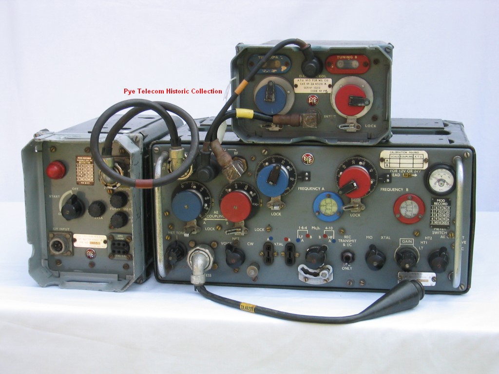
The
equipment,
which
was
designed
by
a
team
including
William
Pannell and Dr. Ladislav
Lax, was of mainly aluminium
construction, was water
resistant,
semi-tropicallised and would
float. It weighed
approximately 30lbs, and was
used as a vehicle mounted
mobile station, a man-pack
set and as an animal-pack
set in both European and Far
East campaigns and later in
the Korean War.
The
transmitter
power
output
was
approximately
1
Watt
into
a
vertical
rod or long wire antenna.
The equipment was
powered by a miniature
rotary transformer mounted
inside the case and supplied
from external 12 Volt
batteries. In 1963 a
transistor dc-dc converter
was designed to replace the
rotary generator. The
example pictured, which
dates from 1953 is fitted
with the transistorised PSU.
See inside top
view and underside
view.
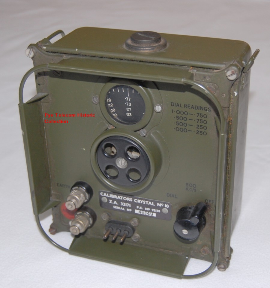
A
separate unit, Crystal
Calibrator
No.
10, was later used as
a frequency setting aid with
WS62 (and with the
C12). From the
Publication Department
master handbook
copies, Bill Pannell
is known to have been the
technical design authority
for Calibrator No. 10.
Production life:
1945 - 1966
Standard
frequency range:
1.6-4 MHz and 4-10 MHz
Transmitter RF
output: 0.8 -
1.5W
Primary model
variants: WS62,
WS62MKI, WS62MK2, also
MK3, MK4, MK5, and MK6
modified versions
Extract from
technical manual:
Yes, to follow
Detailed product
history: See
WS62 history file for
more details
|
|
|
|
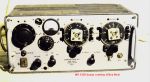
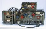
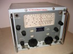
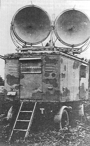
Wireless Set No. 10 (1944)
(part involvement)
 Wireless
Set
No. 10 was the worlds first
transportable multi-channel
Time Division Multiplex
(TDM) microwave radio relay
system. It was
introduced to service in
1944 in time for use after
the D Day landings in
Europe. Wireless
Set
No. 10 was the worlds first
transportable multi-channel
Time Division Multiplex
(TDM) microwave radio relay
system. It was
introduced to service in
1944 in time for use after
the D Day landings in
Europe.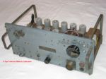 Each
WS10 station was a complete
4GHz transportable transmit
& receive station
mounted in a mobile wheeled
trailer with two 4 foot
parabolic dishes mounted on
the roof. The system
could carry 8 telephone
channels using pulse-width
modulation, and Field
Marshal Bernard Montgomery
later confirmed in writing
the significance of having a
secure line of
communications back to the
UK during the Allied
invasion and subsequent
liberation of Europe.
The
Pye contribution to the WS10
system was the 4GHz receiver
type R10 and matching R10
PSU. GEC designed the
transmitter and TMC designed
the 8 channel time division
multiplex equipment.
Each
WS10 station was a complete
4GHz transportable transmit
& receive station
mounted in a mobile wheeled
trailer with two 4 foot
parabolic dishes mounted on
the roof. The system
could carry 8 telephone
channels using pulse-width
modulation, and Field
Marshal Bernard Montgomery
later confirmed in writing
the significance of having a
secure line of
communications back to the
UK during the Allied
invasion and subsequent
liberation of Europe.
The
Pye contribution to the WS10
system was the 4GHz receiver
type R10 and matching R10
PSU. GEC designed the
transmitter and TMC designed
the 8 channel time division
multiplex equipment.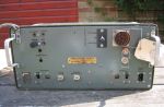 WS
R10 Receiver Unit (right
upper) and R10 Power Supply
Unit (right lower). These
equipments were placed into
military storage in 1956.
WS
R10 Receiver Unit (right
upper) and R10 Power Supply
Unit (right lower). These
equipments were placed into
military storage in 1956.
Equipment
Trailer photo courtesy
of Louis Meulstee
Production
life:
Standard
frequency
range:
Transmitter
RF output:
Extract
from technical manual:
Manual not in Pye Telecom
Collection
:
|
|
|
|
Instrument Landing System
(ILS) (1946 - RAF, 1955 -
ICAO)
 The
Pye
Instrument Landing System
(ILS) was developed after
experience supporting the
RAF BABS system and was
adopted by the Royal Air
Force in 1946. It was
subsequently developed to
enable fully automatic
approach and landing.
Further
development of the design
followed and in 1955 it was
adopted by the ICAO for use
at civil airfields in the UK
and overseas. The
first civil installation was
at Geneva, followed by
Prague, Stansted, London
Heathrow, Moscow etc.
The
equipment was primarily
intended for use as an aid
to the landing of aircraft
under conditions of poor
visibility, but it quickly
became useful as a standard
approach aid in all
circumstances.
The
complete system comprised a
"Localiser" transmitter,
providing guidance in
azimuth along the extended
centre line of the runway; a
"Glidepath" transmitter
provided guidance in
elevation along a sloping
path which intersected
with the ground at the
optimum point of contact,
and three "Marker Beacon"
transmitters spaced along
the approach path which
provided indication of
distance from
touch-down. The
complete system was remotely
monitored from a separate
"Remote Control Console"
which was located in the
main airfield control
buildings.
More
to follow
Production life: 1946
- 1964
Standard
frequency range:
Transmitter RF
output:
Extract
from technical manual:
Yes, to follow The
Pye
Instrument Landing System
(ILS) was developed after
experience supporting the
RAF BABS system and was
adopted by the Royal Air
Force in 1946. It was
subsequently developed to
enable fully automatic
approach and landing.
Further
development of the design
followed and in 1955 it was
adopted by the ICAO for use
at civil airfields in the UK
and overseas. The
first civil installation was
at Geneva, followed by
Prague, Stansted, London
Heathrow, Moscow etc.
The
equipment was primarily
intended for use as an aid
to the landing of aircraft
under conditions of poor
visibility, but it quickly
became useful as a standard
approach aid in all
circumstances.
The
complete system comprised a
"Localiser" transmitter,
providing guidance in
azimuth along the extended
centre line of the runway; a
"Glidepath" transmitter
provided guidance in
elevation along a sloping
path which intersected
with the ground at the
optimum point of contact,
and three "Marker Beacon"
transmitters spaced along
the approach path which
provided indication of
distance from
touch-down. The
complete system was remotely
monitored from a separate
"Remote Control Console"
which was located in the
main airfield control
buildings.
More
to follow
Production life: 1946
- 1964
Standard
frequency range:
Transmitter RF
output:
Extract
from technical manual:
Yes, to follow
|
| Top
of page |
|
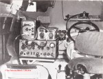
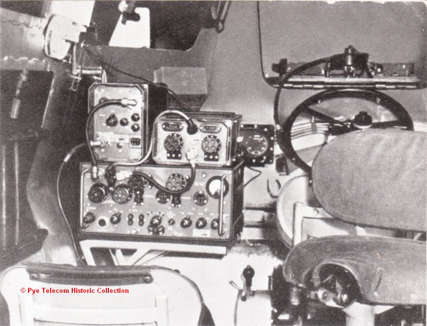
| Wireless Set C12 (1955)
 Wireless
Set
C12 was originally
designed as the PTC202
between about 1948 and
1950 as a private venture
by Pye Ltd to replace the
'A' set and intercom
functions of Wireless Sets
No. 19. Initially
the PTC202 was not
considered for use by the
British Army due to the
War Office preference for
a new concept of
hermetically sealed,
water-proof equipments
(which later came to be
known as Larkspur). Wireless
Set
C12 was originally
designed as the PTC202
between about 1948 and
1950 as a private venture
by Pye Ltd to replace the
'A' set and intercom
functions of Wireless Sets
No. 19. Initially
the PTC202 was not
considered for use by the
British Army due to the
War Office preference for
a new concept of
hermetically sealed,
water-proof equipments
(which later came to be
known as Larkspur).
The
equipment selected to
replace WS19 was
Station Radio C13 from
supplier
BCC
Ltd,
however,
during the early 1950s when
the C13 development program
ran late, the
Pye PTC202 was evaluated and
adopted by the British Army
as Wireless Set C12 and used
as the temporary substitute
for Station Radio C13 in
armoured fighting vehicles.
Due
to
the
slowness
of
the
C13
program
and subsequent
defence cut-backs affecting
the purchase of new
equipments, the C12 remained
in service
until the late 1970s.
Although most C12 equipment
bear the date 1955 it was
first demonstrated by the
Army in July 1953 at
a 3 day exhibition held
at the Royal Aircraft
Establishment, Farnborough
by the Radio Communications
and Electronic Engineering
Association and sponsored by
the Ministry of
Supply. It is pictured
at right fitted into a
Saracen armoured vehicle
during its military trials.
The
equipment
was
constructed
along
similar
lines
to
WS19,
WS22
and WS62, and had the same
overall external dimensions.
It consisted of a
waterproof main transceiver
unit, a separate power
supply unit and an external
aerial tuning unit.
The equipment could be
connected to control wiring
harnesses of the WS19
type or Larkspur type.
It is pictured above
with the WS19 type drop lead
adapter connected. See
inside
top view and underside
view.
The
frequency
range
covered
was
1.6
to
10.0
MHz,
and
the equipment had a
two-channel
electro-mechanical
'flick' tuning system.
The main set used switched
main tuning capacitors, each
with its own colour coded
dial mechanism. The
ATU had twin tuning
inductors switched by relays
under control of the radio
unit. Transmit RF power
output was 5 - 7.5 Watts AM
at 95% modulation and 4 - 8
Watts output on CW. The
equipment was intended to
work into vertical rod
aerials of length between 8
and 32 feet, but would also
operate into a 100 foot
wire. It was claimed
that due to the high level
of modulation achieved, the
station was equivalent to a
WS19 and HP Amplifier No. 2
combination (which gave
about 25 Watts RF output,
although with low level
modulation).
Different
external
power
supply
units
were
provided
for
12
Volt
systems
or
24 Volt systems. Each
used an electro-mechanical
vibrator to provide 250 Volt
HT supplies to the receiver,
and a rotary transformer to
generate the 400 Volt 140mA
supply for the
transmitter. Early 24
volt PSUs ran sufficiently
hot that a manually
controlled cooling fan had
to be added.
Transistorised versions of
both PSU were made available
in the early 1960s. The Crystal Calibrator No. 10 from
Wireless Set No. 62 was used
as an external frequency
reference for the C12, but
modified slightly to
compensate for the different
HT supply voltage.
The
C12
was
manufactured
by
Pye
Ltd
at
a
facility
in
the
Richard Garrett Engineering
Works, Leiston, Ipswich UK,
and later at Pye Scottish
Telecommunications,
Airdrie.
Production life:
1955 - 1965
Standard
frequency range:
1.6 - 4 MHz and 4 - 10 MHz
Transmitter RF
output: 5 -7. 5
Watts at 95% modulation
Primary model
variants: With or
without crystal control
option, 12 Volt or 24 Volt
power supplies,
vibrator/rotary generator
or transistorised inverter
PSUs
Extract from
technical manual:
Yes, to follow,
and technical brochure showing
prototype equipment
Detailed
product
history:
To
follow
|
|
|
|
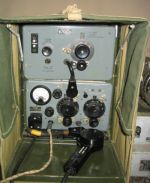
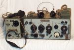
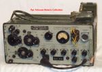
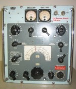
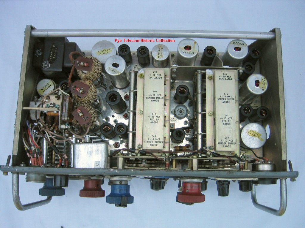
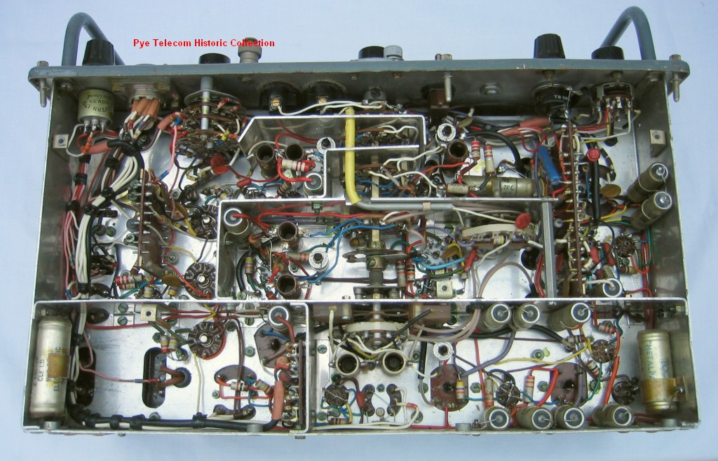
Admiralty Type 619
MF/HF TX & HF RX Type
CAT (1953)
 This
complete station
consisting of an HF
receiver, MF and HF
transmitters and an AC
mains PSU, was the post
war replacement for the
Collins TCS series in
British Admiralty small
and medium sized boats. This
complete station
consisting of an HF
receiver, MF and HF
transmitters and an AC
mains PSU, was the post
war replacement for the
Collins TCS series in
British Admiralty small
and medium sized boats.
It was originally designed
by Pye Telecom at Ditton
Works in 1950, as part of
the Managing Director John
Stanley's enthusiasm to
break into the marine
market. The product
was manufactured at Pye
Marine, Lowestoft
(formerly Reese Mace
Marine) and was sold via
three different
sales distribution
channels to different markets
in parallel, hence
examples can be found
badged as Pye Telecom
Ltd, Pye Marine Ltd,
or Rees Mace Marine Ltd.
A
competing equipment, Type
618, was designed and
produced by Murphy Radio
for the same application.
 Production life:
1953 - 1965
Standard
frequency range:
MF TX 330 - 550 KHz, HF TX
1.5 - 16 MHz, RX 60 KHz -
30 MHz
Transmitter RF
output: MF TX 15
Watts AM, HF TX 40 Watts
AM Production life:
1953 - 1965
Standard
frequency range:
MF TX 330 - 550 KHz, HF TX
1.5 - 16 MHz, RX 60 KHz -
30 MHz
Transmitter RF
output: MF TX 15
Watts AM, HF TX 40 Watts
AM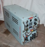 Primary model
variants:
Complete station or
separate receiver only,
with RX PSU
Extract from
technical manual:
B.R. 2169 Yes, to follow
Primary model
variants:
Complete station or
separate receiver only,
with RX PSU
Extract from
technical manual:
B.R. 2169 Yes, to follow
|
|
'Python'
Anti-Tank Guided Weapon
(1956 & 1960)
A
proposed wire-guided
anti-tank missile with a
30lb warhead, with a maximum
range of 4000 yards.
Working models were built
and tested using a 2-stage
rocket motor supplied by the
Bristol Aircraft Company,
Rocket Division. The
design was not adopted by
the Ministry of Supply and
did not start quantity
production. Photo to
follow.
|
|
| Top
of page |
Top
of page
|
Contact
| Home
|
|
V2.0 - Date
11-12-2005 updated
21-06-2021
|
|
Copyright
©
reserved
2002
-
2021
by the authors of the Pye
Telecom Historic Collection,
Cambridge, England
|
|
|
|


