Pye Telecom History Group - Virtual
Pye Museum
|
|||||||
Pye Telecom History Group - Virtual
Pye Museum
|
|||||||
|
|
||||||||||||||||||||||||||||||
|
Please note: The chronological
order is approximate and the research ongoing
|
||||||||||||||||||||||||||||||
PTC
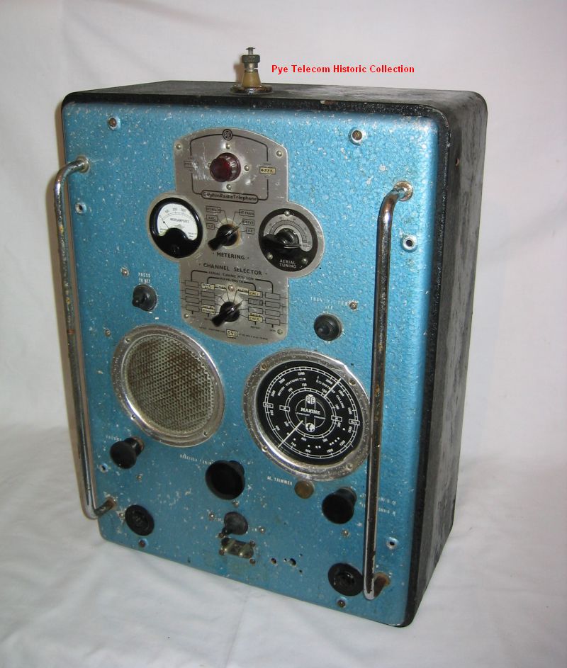
110/PTC797/PTC798/PM120 Dolphin Marine HF TX/RX (1948)
 The Dolphin was an
HF marine radiotelephone which was introduced in
1948 to meet the need (anticipated by Pye Group
Chairman C.O. Stanley) for improved communications
between small vessels which would arise after World
War II. The Dolphin was an
HF marine radiotelephone which was introduced in
1948 to meet the need (anticipated by Pye Group
Chairman C.O. Stanley) for improved communications
between small vessels which would arise after World
War II.The receiver section was a 5 valve superhet covering 530 - 1600 KHz and 1520 KHz - 3800 KHz in two tunable ranges using miniature 1.5 Volt valves. Later models added a third frequency range to the receiver for the reception of navigation signals from the 'Consol' system. A vibrator PSU was fitted operating from a 12 Volt DC supply. The transmitter was a 4 valve, 8 channel, crystal controlled unit covering 1520 - 3800 KHz using an 807 valve in the PA and was fitted with a rotary transformer PSU (motor-generator) to generate the 450 Volts HT for the transmitter. Various components from the Pye war-time military wireless sets were used in the Dolphin. The equipment was intended to be used on small boats, yachts and trawlers with a long wire antenna in a 'T' or inverted 'L' configuration. The equipment evolved through three different model variants. Early MKI and MKII models (PTC110) used an aluminium guard rail around the front panel to protect the controls (rather like wireless Set No. 62) but later models simply used two large chromium handles. Later models (PTC 797/8 or PM120A) were available for operation on 12 Volts or 24 Volts. |
||||||||||||||||||||||||||||||
| Top of page | ||||||||||||||||||||||||||||||
|
|
||||||||||||||||||||||||||||||
PM121/PM231/PM232
Consol Marine RX (1950)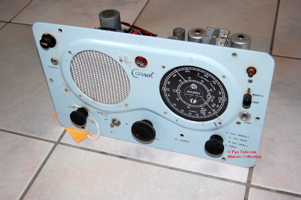 The Pye Marine 'Consol' receiver
was a general purpose marine receiver covering
the frequency ranges 150 - 348 KHz, 530 - 1600 KHz and
1520 - 3800 KHz. It was also equipped for
use with the Consol HF long range navigation system
which was operational from the mid 1930s to the early
1980s. When switched to the 'Consol' position a
Beat Frequency Oscillator (BFO) was operational to
allow the heterodyne notes from the Consol signals to
be heard. The Pye Marine 'Consol' receiver
was a general purpose marine receiver covering
the frequency ranges 150 - 348 KHz, 530 - 1600 KHz and
1520 - 3800 KHz. It was also equipped for
use with the Consol HF long range navigation system
which was operational from the mid 1930s to the early
1980s. When switched to the 'Consol' position a
Beat Frequency Oscillator (BFO) was operational to
allow the heterodyne notes from the Consol signals to
be heard.The Consol system transmitted on frequencies between 257 and 363 KHz, and like Gee, was classed as a hyperbolic navigation system, since a position line on a map is derived from the difference in arrival time of synchronised transmissions. Versions of the Pye Consol receiver were available to operate from a 12 volt or 24 Volt dc supply using an internal vibrator power supply. Early production equipment were sold with the Pye Marine badge, but later equipments were sold under the name Pye Telecommunications. From inspection of three different examples of the Consol receiver and comparison with the original PTC110 Dolphin equipment, it is deduced that the PM121 series equipment is basically the complete receiver section from the lower half of the MKII or MKIII Pye Dolphin, with minor changes to widen the frequency coverage and to add a BFO compared to the MKI Dolphin. See inside view. |
||||||||||||||||||||||||||||||
| Top of page | ||||||||||||||||||||||||||||||
|
|
||||||||||||||||||||||||||||||
| PTC931 4ch HF TX info to follow |
||||||||||||||||||||||||||||||
| Top of page | ||||||||||||||||||||||||||||||
|
|
||||||||||||||||||||||||||||||
| PTC941 4 ch HF RX info to follow |
||||||||||||||||||||||||||||||
| Top of page | ||||||||||||||||||||||||||||||
|
|
||||||||||||||||||||||||||||||
Admiralty
Type 619 MF/HF TX & HF RX Type CAT (1953)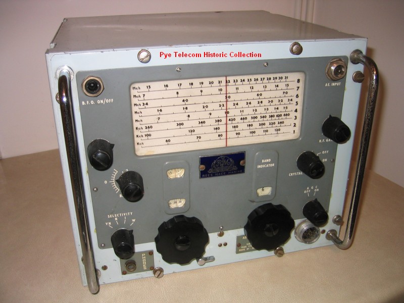 This
complete station consisting of an HF receiver, MF
and HF transmitters and an AC mains PSU, was the
post war replacement for the Collins TCS series in
British Admiralty small and medium sized
boats. This
complete station consisting of an HF receiver, MF
and HF transmitters and an AC mains PSU, was the
post war replacement for the Collins TCS series in
British Admiralty small and medium sized
boats. It was originally designed by Pye Telecom at Ditton Works in 1950, as part of the Managing Director John Stanley's enthusiasm to break into the marine market. The product was manufactured at Pye Marine, Lowestoft (formerly Reese Mace Marine) and was sold via three different distribution channels to different markets in parallel, hence examples can be found badged as Pye Telecom Ltd, Pye Marine Ltd, or Rees Mace Marine Ltd. The equipment was also supplied to other NATO allies such as the Netherlands. 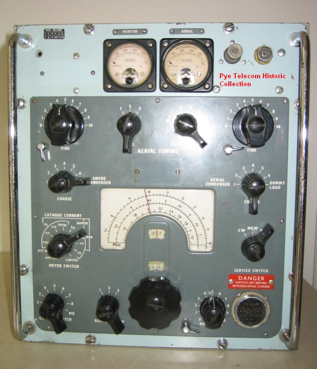 Production life:
1953 - 1965 Production life:
1953 - 1965Standard frequency range: MF Tex 330 - 550 KHz, HF TX 1.5 - 16 MHz, RX 60 KHz - 30 MHz Transmitter RF output: MF TX 15 Watts AM, HF TX 40 Watts AM Primary model variants: Separate receiver only, with RX PSU Extract from brochure, Pye technical manual and Admiralty BR 2169, to follow |
||||||||||||||||||||||||||||||
| Top of page | ||||||||||||||||||||||||||||||
|
|
||||||||||||||||||||||||||||||
| PTC791/2
Swordfish Marine HF TX/RX The Pye Swordfish was a series of marine HF transmitter-receivers intended for compulsory installation in Merchant Ships which were subject to the British Post Office Marine regulations. info to follow |
||||||||||||||||||||||||||||||
| Top of page | ||||||||||||||||||||||||||||||
|
|
||||||||||||||||||||||||||||||
| Hornet Marine HF
TX/RX info to follow |
||||||||||||||||||||||||||||||
| Top of page | ||||||||||||||||||||||||||||||
|
|
||||||||||||||||||||||||||||||
| PTC1090/1 Marine
Depth Sounder info to follow |
||||||||||||||||||||||||||||||
| Top of page | ||||||||||||||||||||||||||||||
|
|
||||||||||||||||||||||||||||||
| PTC981 Marine HF
RX info to follow |
||||||||||||||||||||||||||||||
| Top of page | ||||||||||||||||||||||||||||||
|
|
||||||||||||||||||||||||||||||
PTC986 Mercury HF
TX/RX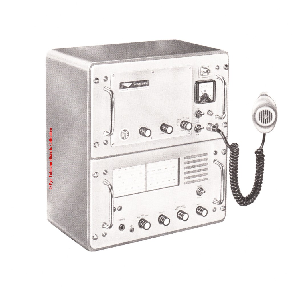 The
PTC986 Mercury was an HF transmitter-receiver intended
for land fixed and mobile use in the export markets
where long range communication was required. It
was a variation of the PM125 Hamble design. The
PTC986 Mercury was an HF transmitter-receiver intended
for land fixed and mobile use in the export markets
where long range communication was required. It
was a variation of the PM125 Hamble design.The equipment had a transistorised, tunable receiver and an 8 channel crystal controlled transmitter. The RF power output was 20 Watts AM or CW into 50 Ohms. The internal power supply was also transistorised. The frequencies covered were 535 - 1605 KHz, 1.6 - 3.8 MHz and 3.8 - 10.0 MHz. 12 Volt and 24 Volt DC powered versions were available. |
||||||||||||||||||||||||||||||
| Top of page | ||||||||||||||||||||||||||||||
|
|
||||||||||||||||||||||||||||||
PM125 Hamble
Marine HF TX/RX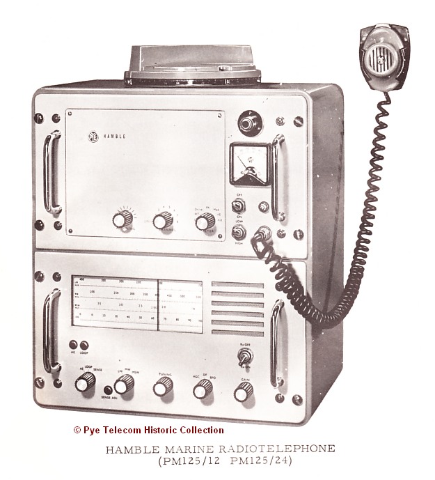 The
PM125 Hamble was a marine HF transmitter-receiver
intended for voluntary installation in boats and yachts
which were subject to the British Post Office Marine
regulations. The
PM125 Hamble was a marine HF transmitter-receiver
intended for voluntary installation in boats and yachts
which were subject to the British Post Office Marine
regulations.The equipment had a transistorised, tunable receiver and an 8 channel crystal controlled transmitter. The RF power output was 20 Watts AM or CW into 50 Ohms. The internal power supply was also transistorised. A rotatable ferrite bar antenna for direction finding was mounted on the top of the cabinet. The frequencies covered were 150 - 400 KHz, 535 - 1605 KHz and 1.6 - 3.8 MHz. Reception of the Consol navigation system signals were possible with the equipment. 12 Volt and 24 Volt DC powered versions were available. |
||||||||||||||||||||||||||||||
| Top of page | ||||||||||||||||||||||||||||||
|
|
||||||||||||||||||||||||||||||
| PM140 Foreland
Marine HF RX The Pye Foreland was the receiver section of the Pye Hamble TX/RX but mounted in a separate cabinet. It was fitted with a rotatable ferrite bar DF aerial. |
||||||||||||||||||||||||||||||
| Top of page | ||||||||||||||||||||||||||||||
|
|
||||||||||||||||||||||||||||||
MRT35/MRT60
Seaphone Marine HF TX/RX (1966)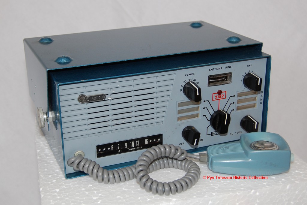 The
MRT35 and MRT60 Seaphone equipment were 7 channel,
crystal controlled, solid-state marine
transmitter/receivers which also contained a tunable
receiver for reception of medium wave broadcast
frequencies. The
MRT35 and MRT60 Seaphone equipment were 7 channel,
crystal controlled, solid-state marine
transmitter/receivers which also contained a tunable
receiver for reception of medium wave broadcast
frequencies.The equipment was designed and produced by Pye New Zealand. The frequency coverage of the TX/RX section was 2.0 - 2.9 MHz. The transmitter output of the MRT35 was 10 Watts and the MRT60 was 20 Watts (measured into 200pF in series with 10 Ohms). Copy of brochure to follow |
||||||||||||||||||||||||||||||
| Top of page | ||||||||||||||||||||||||||||||
|
|
||||||||||||||||||||||||||||||
PTC984 Solent
Marine HF DF RX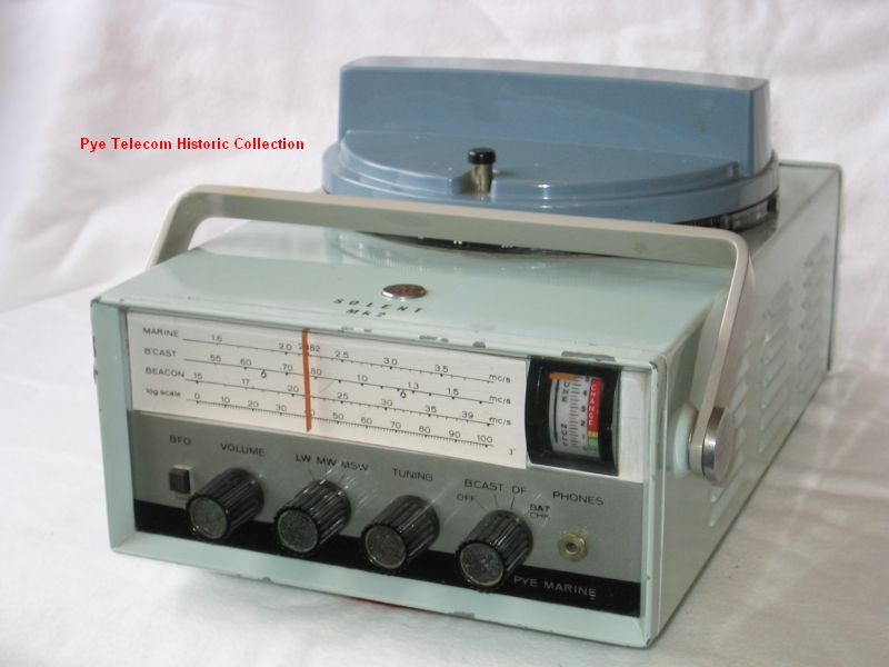 The Pye PTC984 Solent was a
transistorised battery-powered HF marine receiver with
direction finding facilities and a rotatable ferrite
bar DF antenna (calibrated in degrees) mounted on the
top of the case. The Pye PTC984 Solent was a
transistorised battery-powered HF marine receiver with
direction finding facilities and a rotatable ferrite
bar DF antenna (calibrated in degrees) mounted on the
top of the case.Examples can be found badged as Pye or as ARC (Aircraft Radio Corporation, Boonton, New Jersey, USA). More details and photos to follow |
||||||||||||||||||||||||||||||
| Top of page | ||||||||||||||||||||||||||||||
|
|
||||||||||||||||||||||||||||||
SSB125 &
SSB125T HF SSB Mobile (1963)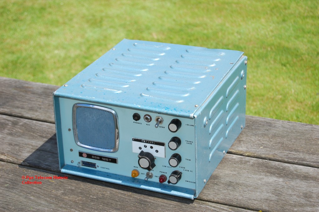 The SSB125 was an
HF SSB transmitter-receiver for mobile or fixed
applications which produced an RF output of 125 Watts
peak envelope power (PEP). The
equipment was suitable for local operation or remote
control using a modified Pye Cambridge control box,
microphone and loudspeaker. The equipment could
operate on any one of four crystal
controlled spot frequencies. The SSB125 was an
HF SSB transmitter-receiver for mobile or fixed
applications which produced an RF output of 125 Watts
peak envelope power (PEP). The
equipment was suitable for local operation or remote
control using a modified Pye Cambridge control box,
microphone and loudspeaker. The equipment could
operate on any one of four crystal
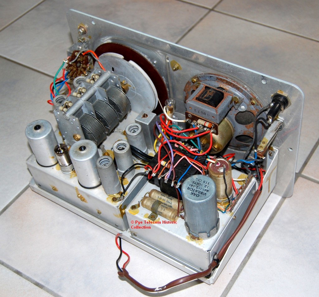
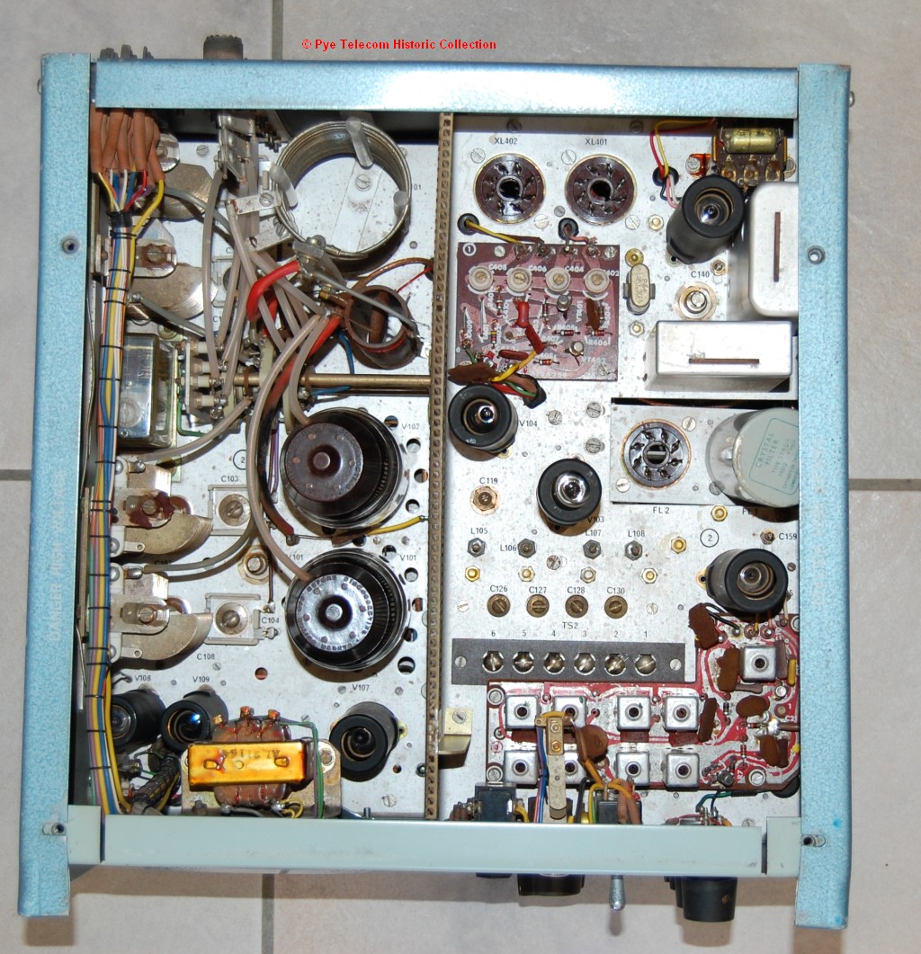
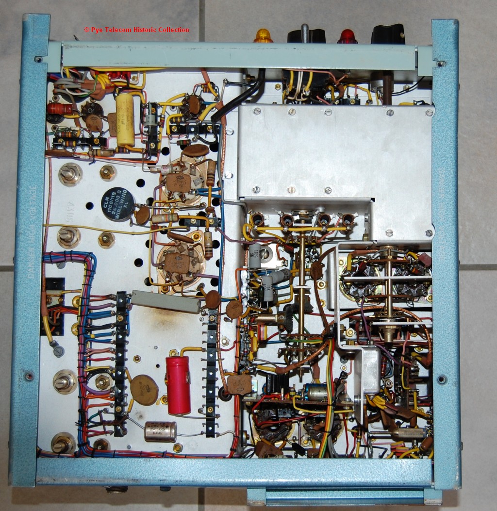
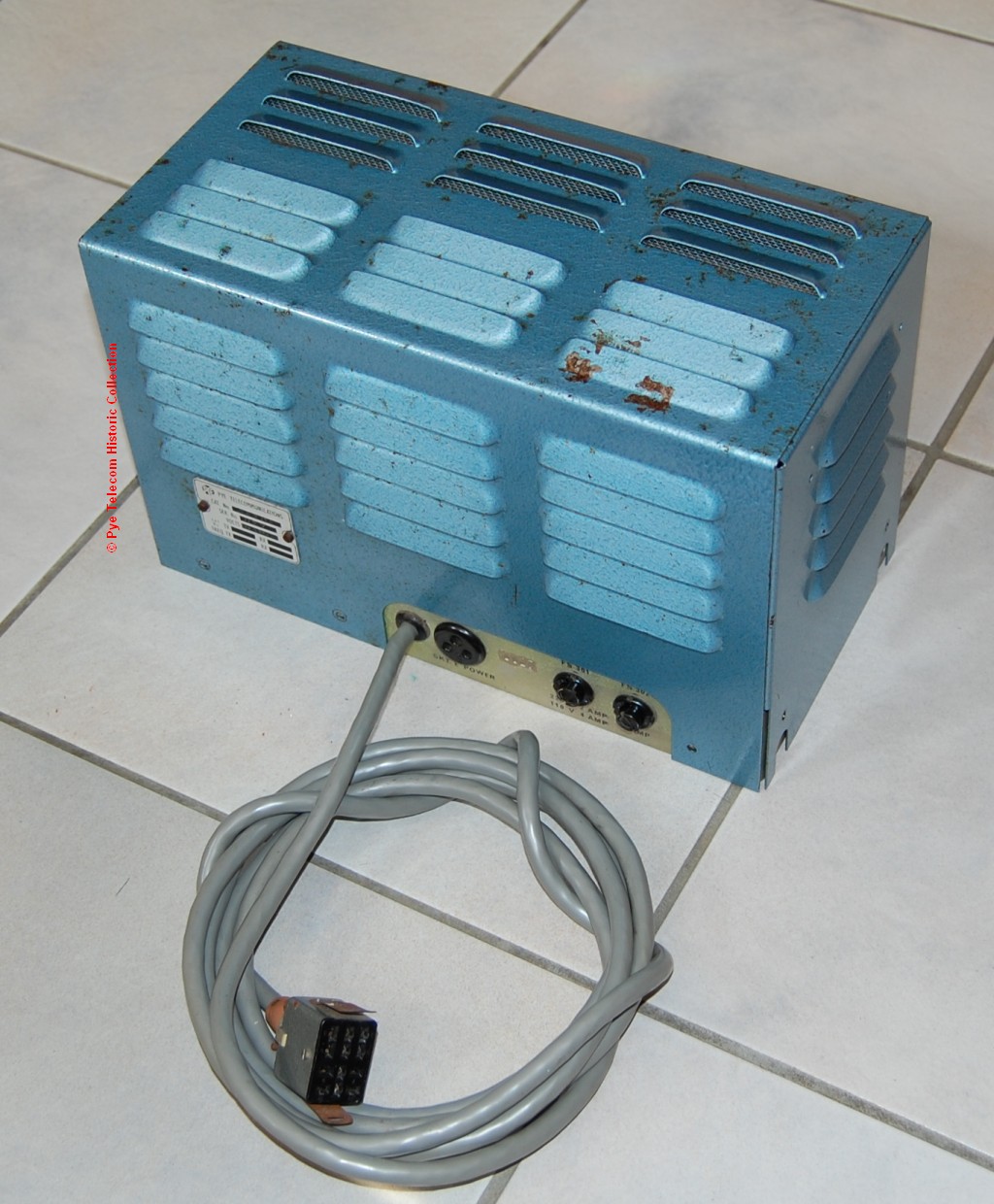
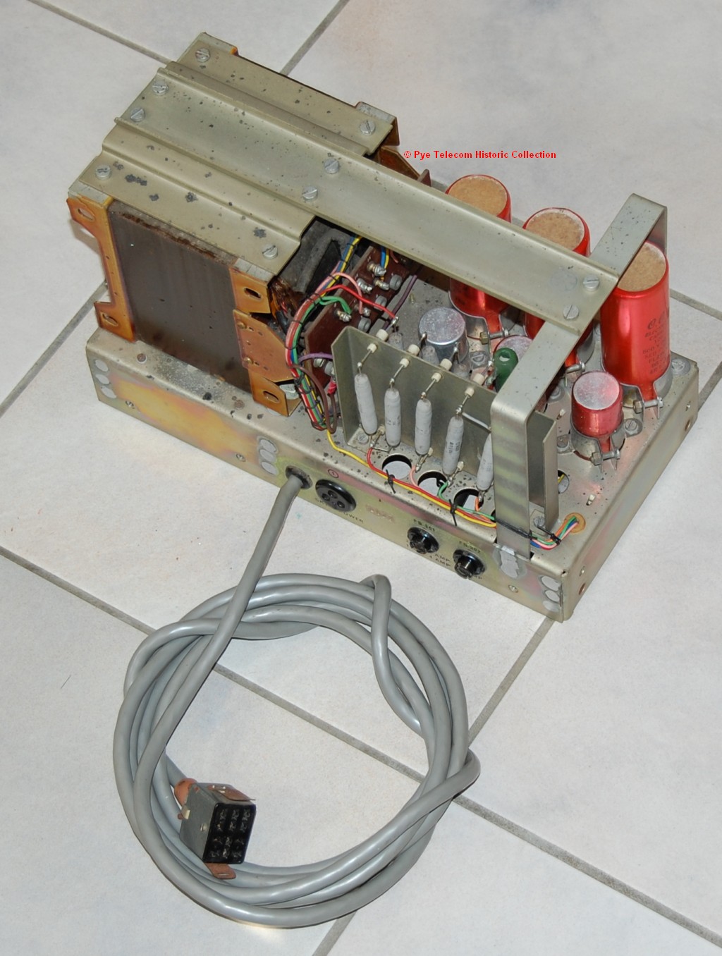
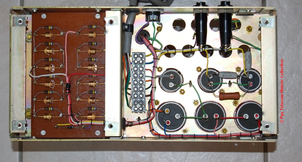
controlled spot frequencies.The SSB125 equipment was based on the RCA SSB-5 equipment circuit design and manufactured under license by Pye Telecom in the UK, using Pye designed mechanics. This enabled Pye to supply HF mobile equipment to customers requiring longer range communication than provided by normal VHF or UHF systems. The original SSB125 was an all-valve equipment whereas the later SSB125T was fitted with a transistorised receiver. See inside top view of transceiver unit and underneath view. A separate12 Volt, 24 Volt or AC mains power supply was used. See inside top view and underside view of the mains PSU for the original SSB125 with valve receiver. Grateful thanks to John Farnell VK6JGF for sending this equipment "back home" from Australia to join the collection, and to Brian Armstrong G3EDD for donating the power supply. More details to follow. |
||||||||||||||||||||||||||||||
| Top of page | ||||||||||||||||||||||||||||||
|
|
||||||||||||||||||||||||||||||
SSB130M Mobile
& SSB130F Fixed Station (1970)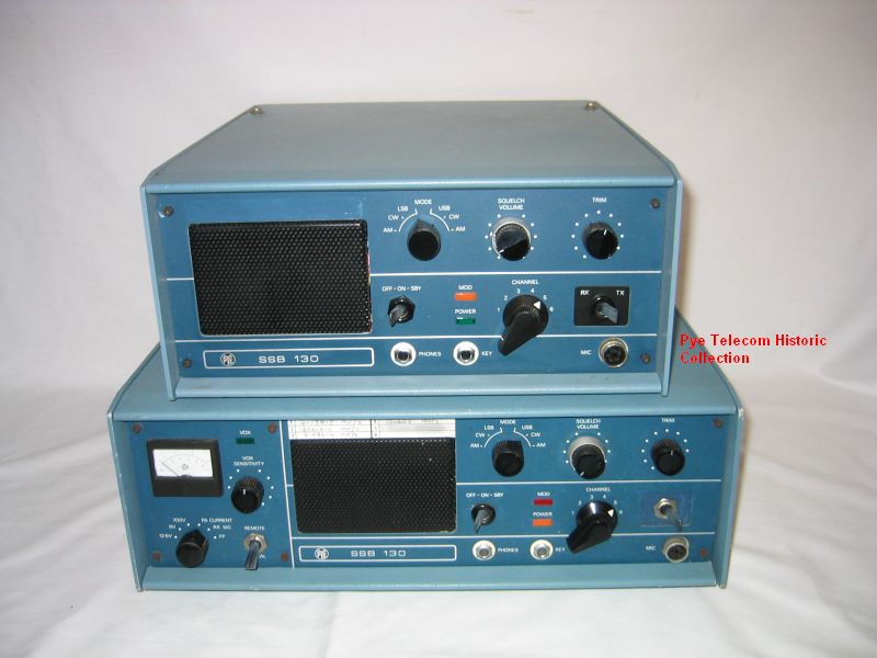 The
SSB130 was an HF SSB transmitter-receiver using a
hybrid semiconductor and valve design to generate 130
Watts peak envelope power (PEP). It
also had AM and CW facilities. The simplex
frequency range covered was 2.0 to 15 MHz using upper
or lower sideband transmission. The equipment
was all-transistorised except for the two power
amplifier valves. Crystal
controlled operation on spot frequencies was the
method of frequency generation and the sets were
usually manufactured to operate with 2 channels in
each of the 2-4 MHz, 4-8 MHz and 8-15 MHz frequency
bands to allow for propagation changes over a 24 hour
period.. The
SSB130 was an HF SSB transmitter-receiver using a
hybrid semiconductor and valve design to generate 130
Watts peak envelope power (PEP). It
also had AM and CW facilities. The simplex
frequency range covered was 2.0 to 15 MHz using upper
or lower sideband transmission. The equipment
was all-transistorised except for the two power
amplifier valves. Crystal
controlled operation on spot frequencies was the
method of frequency generation and the sets were
usually manufactured to operate with 2 channels in
each of the 2-4 MHz, 4-8 MHz and 8-15 MHz frequency
bands to allow for propagation changes over a 24 hour
period..There were two versions of the equipment; the SSB130M mobile version suitable for local or extension control and the SSB130F fixed station version with front panel metering, full remote control and phone-patch facilities. When operated from 12 or 24 Volts DC, a transistor inverter PSU was fitted into a large recess at the rear of the equipment. For AC mains operation a separate PSU was used. When used in remote control mode a modified Pye Westminster control box, microphone and loudspeaker was used. A tele-radio interface unit was available to allow connection to telephone lines, which I will photograph when I can find the unit. Unlike the SSB125 equipment, the SSB130 was completely designed by engineers in the Fixed Station Laboratory of Pye Telecom in Cambridge. More photos to follow |
||||||||||||||||||||||||||||||
| Top of page | ||||||||||||||||||||||||||||||
|
|
||||||||||||||||||||||||||||||
SSB170 HF SSB Mobile
(1978)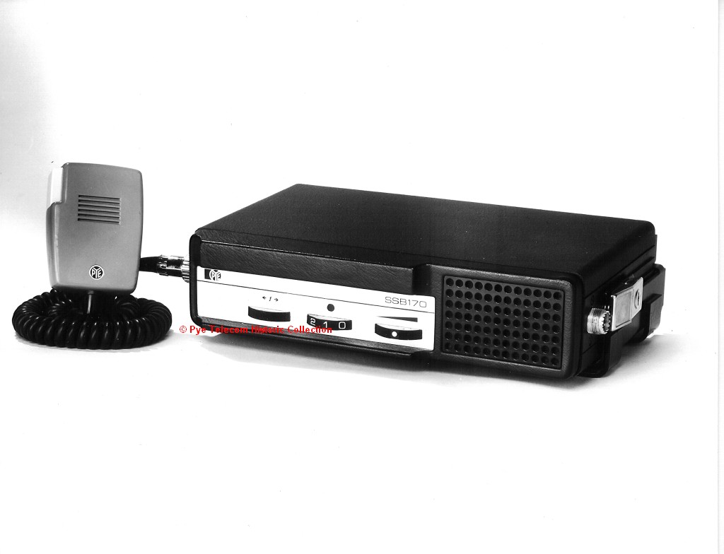 The SSB170 was a low
power HF SSB transmitter-receiver designed for
mobile or fixed-mobile applications.
Constructed using the mechanics from the MF5 and
MF25 Europa family of equipment, it generated an
output power of 20 Watts peak envelope power (PEP).
The simplex frequency
range covered was 2.0 to 15 MHz.
The equipment could operate on 4 crystal controlled
channels and was designed for USB operation
only. The SSB170 normally operated directly
from a vehicle 12 Volt DC battery supply. For
operation from 24 Volts, floating earth supplies or
AC mains, the standard Europa range PSU accessories
were used. The SSB170 was a low
power HF SSB transmitter-receiver designed for
mobile or fixed-mobile applications.
Constructed using the mechanics from the MF5 and
MF25 Europa family of equipment, it generated an
output power of 20 Watts peak envelope power (PEP).
The simplex frequency
range covered was 2.0 to 15 MHz.
The equipment could operate on 4 crystal controlled
channels and was designed for USB operation
only. The SSB170 normally operated directly
from a vehicle 12 Volt DC battery supply. For
operation from 24 Volts, floating earth supplies or
AC mains, the standard Europa range PSU accessories
were used.More info and new photos to follow |
||||||||||||||||||||||||||||||
| Top of page | ||||||||||||||||||||||||||||||
|
|
||||||||||||||||||||||||||||||
SSB200
&
SSB210
HF
SSB
Mobile (1984) 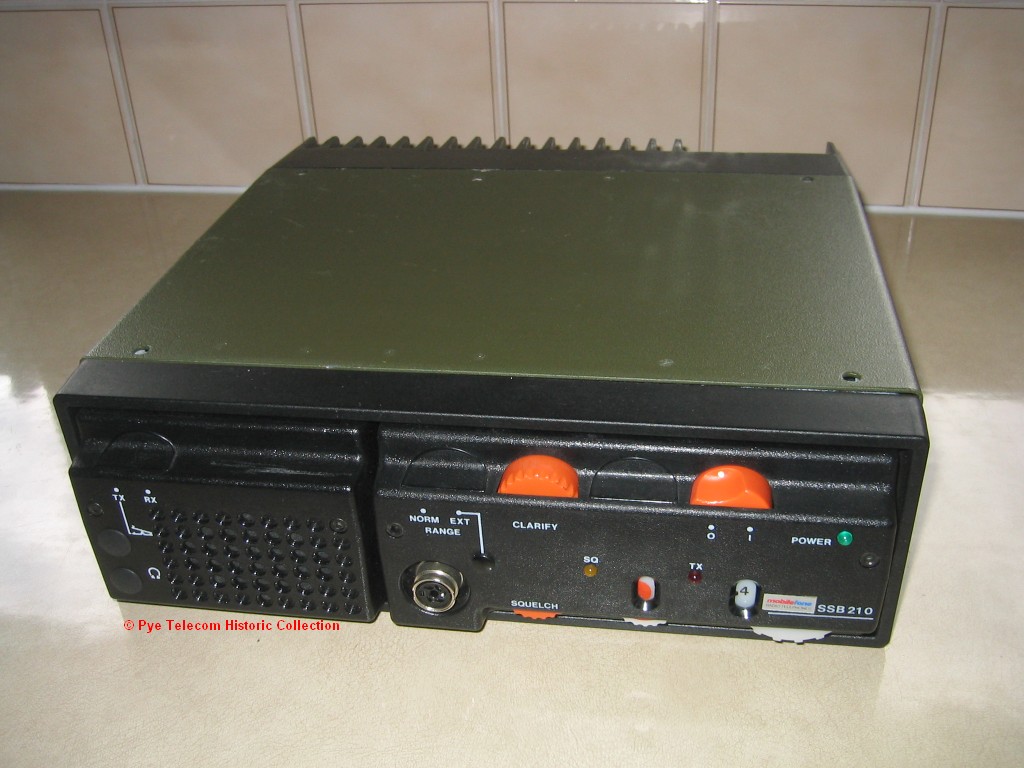 The SSB200 and SSB210
were fully solid-state HF SSB transmitter-receivers
generating 100 Watt peak envelope power (PEP) over the
frequency range 2-15MHz in 5 bands. USB, LSB and
CW modes of operation were available plus reception of
AM transmissions. The SSB200 model could operate
on 4 separate channels and the SSB210 on 11 channels. The SSB200 and SSB210
were fully solid-state HF SSB transmitter-receivers
generating 100 Watt peak envelope power (PEP) over the
frequency range 2-15MHz in 5 bands. USB, LSB and
CW modes of operation were available plus reception of
AM transmissions. The SSB200 model could operate
on 4 separate channels and the SSB210 on 11 channels.The equipment operated from a 12 Volt DC supply provided either by the vehicle battery in mobile installations or a separate AC mains powered 12 Volt supply for fixed station use. Draft photo, more details and photos to follow |
||||||||||||||||||||||||||||||
| Top of page | ||||||||||||||||||||||||||||||
|
|
||||||||||||||||||||||||||||||
| SSB220 HF SSB
Mobile (1987) An all solid state synthesised HF SSB mobile transceiver, supplied to Philips as an OEM purchase by the manufacturers SEA Inc of the USA. The equipment is a cosmetic variant of the SEA222 model. |
||||||||||||||||||||||||||||||
| Top of page | ||||||||||||||||||||||||||||||
|
|
||||||||||||||||||||||||||||||
|
Top of page
|
| Home
|
|
V2.0 - Date 2-03-2007 updated 30-12-2012 |
|
Copyright © reserved 2002 - 2009 Pye Telecom History Group, Cambridge, England |
