Pye Telecom History Group - Virtual
Pye Museum
|
||||||||
Pye Telecom History Group - Virtual
Pye Museum
|
||||||||
|
|
|||||||||||||||||||||||||||||
|
Please note: The chronological
order is approximate and the research on-going
|
|||||||||||||||||||||||||||||
| PTC400/401 Control
Units
& PTC255/256/265 Control
Panels (1947) This was the
first generation of operator control units and control
panels designed to support the original Pye fixed
stations types PTC104, PTC104A, PTC105, PTC105A,
PTC106 and PTC106A.
Starting with the launch of the Pye Radio-telephone system concept in 1947, two types of operator control arrangements were made available. Extension control where the fixed station transmitter/receiver and the operator control unit were located within 200 feet of one another, and remote control where the fixed station was located a considerable distance away from the control operator, and Post Office telephone lines were used to interconnect the two sites. Both types of controller were small desk-top units constructed in veneered wood cabinets, containing a loudspeaker, volume control and transmit/receive switch. A suitable control interface panel was fitted to the fixed station cabinet to receive commands from the control unit. PTC400 Extension Controller 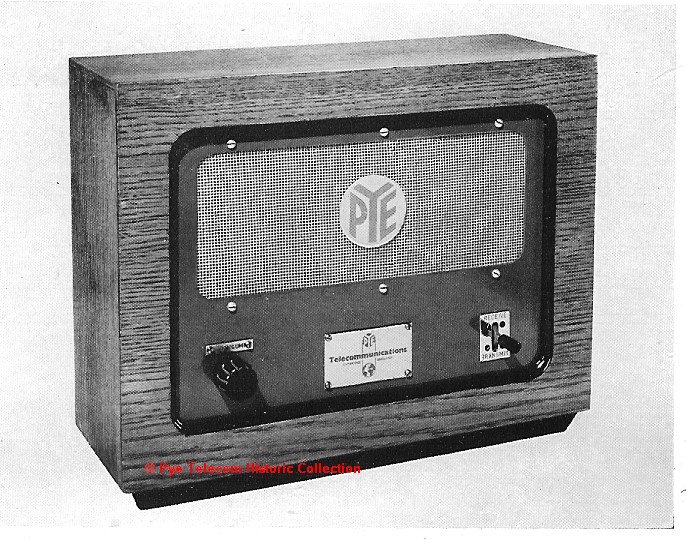 In
the case of the PTC400 extension control units, either
an internal microphone or an external telephone
handset was used by the control operator. A
multi-way cable interconnected the control unit and
the PTC255 single-operator extension control panel, or
the PTC265 double-operator extension control panel. In
the case of the PTC400 extension control units, either
an internal microphone or an external telephone
handset was used by the control operator. A
multi-way cable interconnected the control unit and
the PTC255 single-operator extension control panel, or
the PTC265 double-operator extension control panel.PTC401 Remote Controller 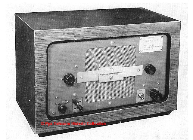 The
PTC401 remote control unit was constructed in a
similar manner to the PTC400 above and could be used
for simplex or duplex applications using a single
telephone line, or a pair of lines in the case of
duplex operation. A PTC256 telephone line
interface panel containing switching relays and line
matching transformers was fitted to the fixed station
cabinet. The
PTC401 remote control unit was constructed in a
similar manner to the PTC400 above and could be used
for simplex or duplex applications using a single
telephone line, or a pair of lines in the case of
duplex operation. A PTC256 telephone line
interface panel containing switching relays and line
matching transformers was fitted to the fixed station
cabinet. |
|||||||||||||||||||||||||||||
| Top of page | |||||||||||||||||||||||||||||
|
|
|||||||||||||||||||||||||||||
PTC406/408 Control
Units &
PTC255/407 Control Panels (1950)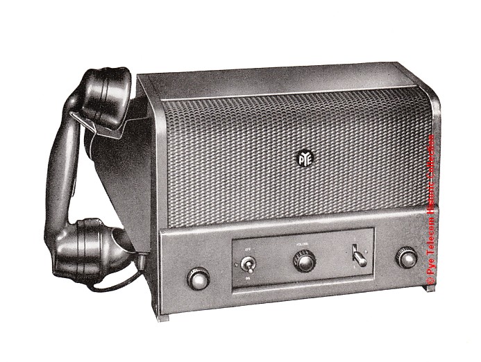 This second
generation of control units and control panels were
designed to work with the second generation
PTC703/PTC704 15 Watt fixed stations or the higher
power PTC300 100 Watt transmitter. As with the
first generation equipments, extension control or
remote control of both simplex or duplex fixed
stations was possible. The operator control
instrument was either a telephone handset or a
separate desk-top stand microphone. This second
generation of control units and control panels were
designed to work with the second generation
PTC703/PTC704 15 Watt fixed stations or the higher
power PTC300 100 Watt transmitter. As with the
first generation equipments, extension control or
remote control of both simplex or duplex fixed
stations was possible. The operator control
instrument was either a telephone handset or a
separate desk-top stand microphone.The desk-top control unit was constructed from thick Bakelite moulded panels bolted together, with a curved front cover of expanded aluminium gauze. This construction was borrowed from a Pye Ltd domestic receiver which was finished in a gold spray paint finish. Early examples of the PTC406/408 equipments were also finished in gold but later changed to dimenso blue. A gold finished example will be photographed shortly. See also the photographs of the PTC411 below which used the same mechanics. |
|||||||||||||||||||||||||||||
| Top of page | |||||||||||||||||||||||||||||
|
|
|||||||||||||||||||||||||||||
PTC408/411 Control Units
& PTC407/255 Control Panels (1952)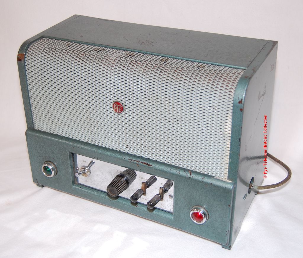 An
electrically improved version of the second generation
PTC406/408 operator control units using miniature
all-glass valves instead of the older International
Octal valves. This series of controllers was in
production from 1952 until about 1963. An
electrically improved version of the second generation
PTC406/408 operator control units using miniature
all-glass valves instead of the older International
Octal valves. This series of controllers was in
production from 1952 until about 1963. |
|||||||||||||||||||||||||||||
| Top of page | |||||||||||||||||||||||||||||
|
|
|||||||||||||||||||||||||||||
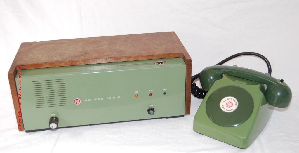
PTC455 Extension
Control Unit & PTC456 Control Panel (1954)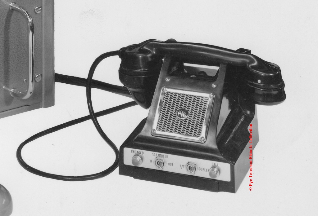 The
PTC455 was a simple and low cost radiotelephone
extension controller constructed from a standard
telephone handset and base which also contained a
small loudspeaker. The PTC456 was the matching
19 inch extension control panel fitted into the fixed
station transmitter-receiver cabinet.
This arrangement was suitable for use where the
distance between the operator control point and the
radiotelephone equipment was not greater than 200
feet. The PTC455 was
suitable for controlling the PTC703/PTC704,
PTC714/PTC715 equipment. The
PTC455 was a simple and low cost radiotelephone
extension controller constructed from a standard
telephone handset and base which also contained a
small loudspeaker. The PTC456 was the matching
19 inch extension control panel fitted into the fixed
station transmitter-receiver cabinet.
This arrangement was suitable for use where the
distance between the operator control point and the
radiotelephone equipment was not greater than 200
feet. The PTC455 was
suitable for controlling the PTC703/PTC704,
PTC714/PTC715 equipment. 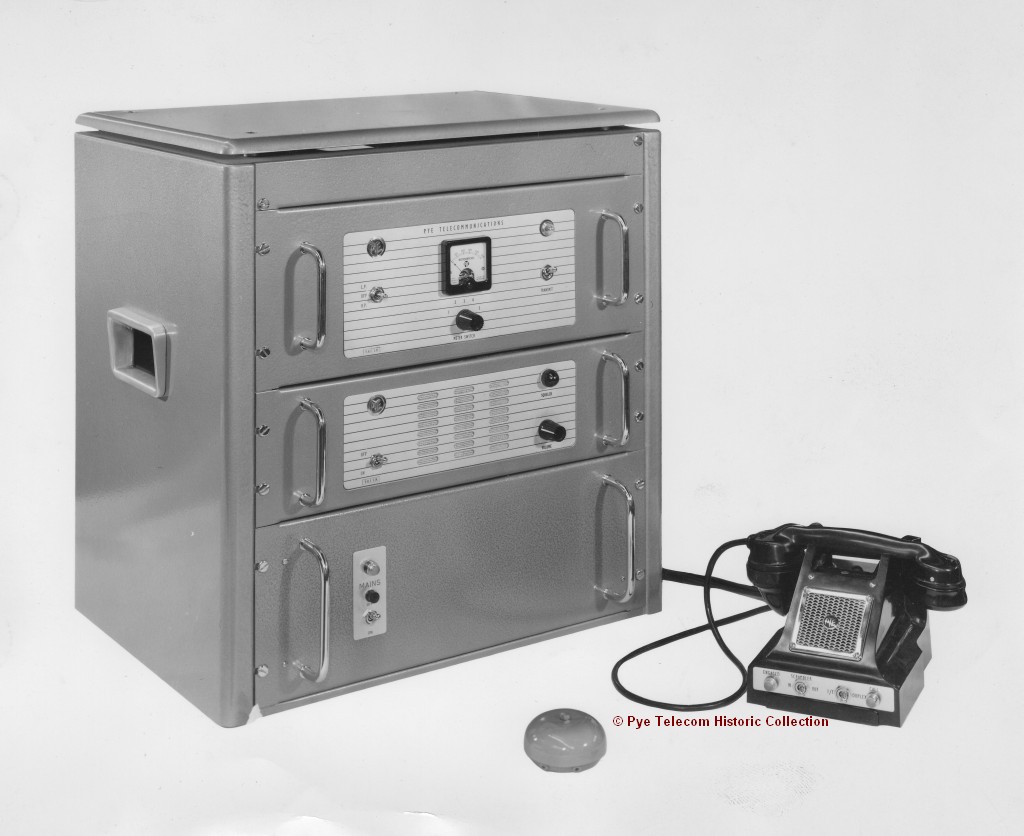 Equipment type PTC455Z was a later version of the above suitable to operate with the PTC723, PTC753, and PTC8701/2, PTC2701/2, PTC8701/2 Ranger based fixed stations. A wide range of variants of this simple telephone handset and base type controller was used until the early 1960s. The example illustrated above and at right is from the radio system for UAR in 1962. |
|||||||||||||||||||||||||||||
| Top of page | |||||||||||||||||||||||||||||
|
|
|||||||||||||||||||||||||||||
PTC411/A/B/B-4
Remote Control Units & PTC457/A/B/B-4 Control
Panels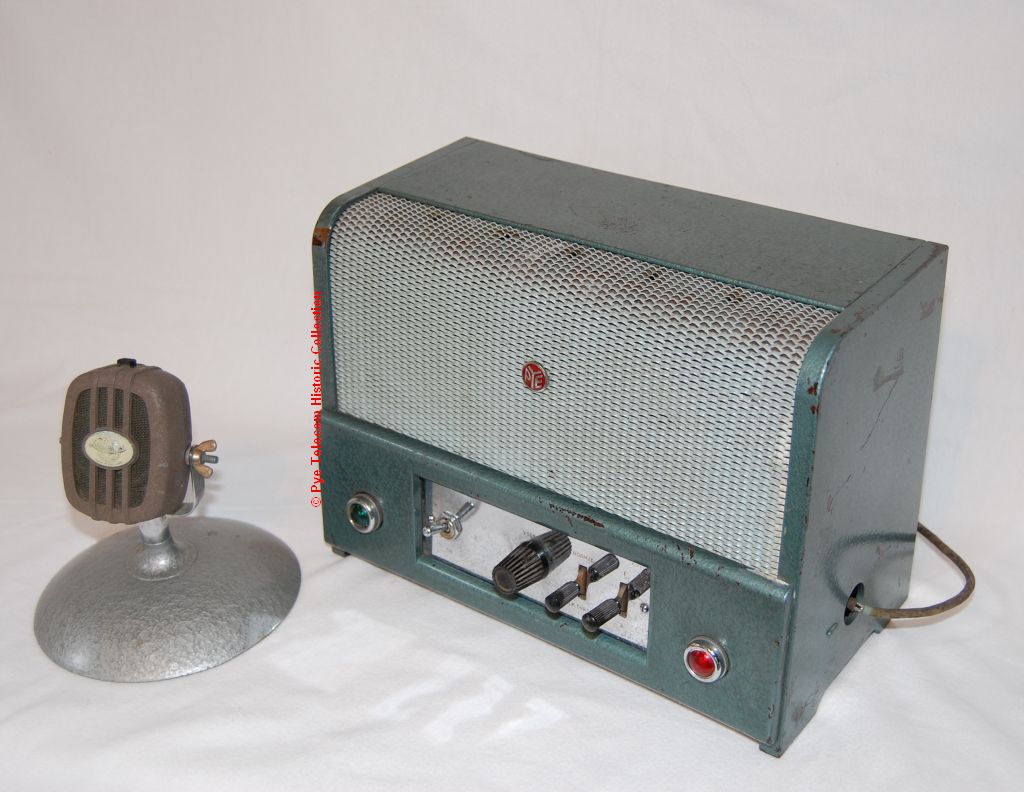 This
was a further development of the existing PTC411 &
PTC457 remote control equipment and was available with
either a This
was a further development of the existing PTC411 &
PTC457 remote control equipment and was available with
either a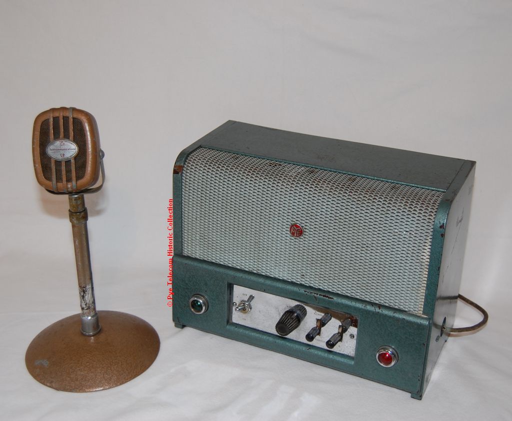 telephone handset or a high quality Lustraphone desk
microphone as the operator control instrument.
The Lustraphone microphones were available with either
a short or long stand. The equipment was
suitable for either simplex or duplex (2 wire or 4
wire circuits) operation.
telephone handset or a high quality Lustraphone desk
microphone as the operator control instrument.
The Lustraphone microphones were available with either
a short or long stand. The equipment was
suitable for either simplex or duplex (2 wire or 4
wire circuits) operation. |
|||||||||||||||||||||||||||||
| Top of page | |||||||||||||||||||||||||||||
|
|
|||||||||||||||||||||||||||||
PTC411X
Remote
Control Unit & PTC457/8 Remote Control Panel
(1958)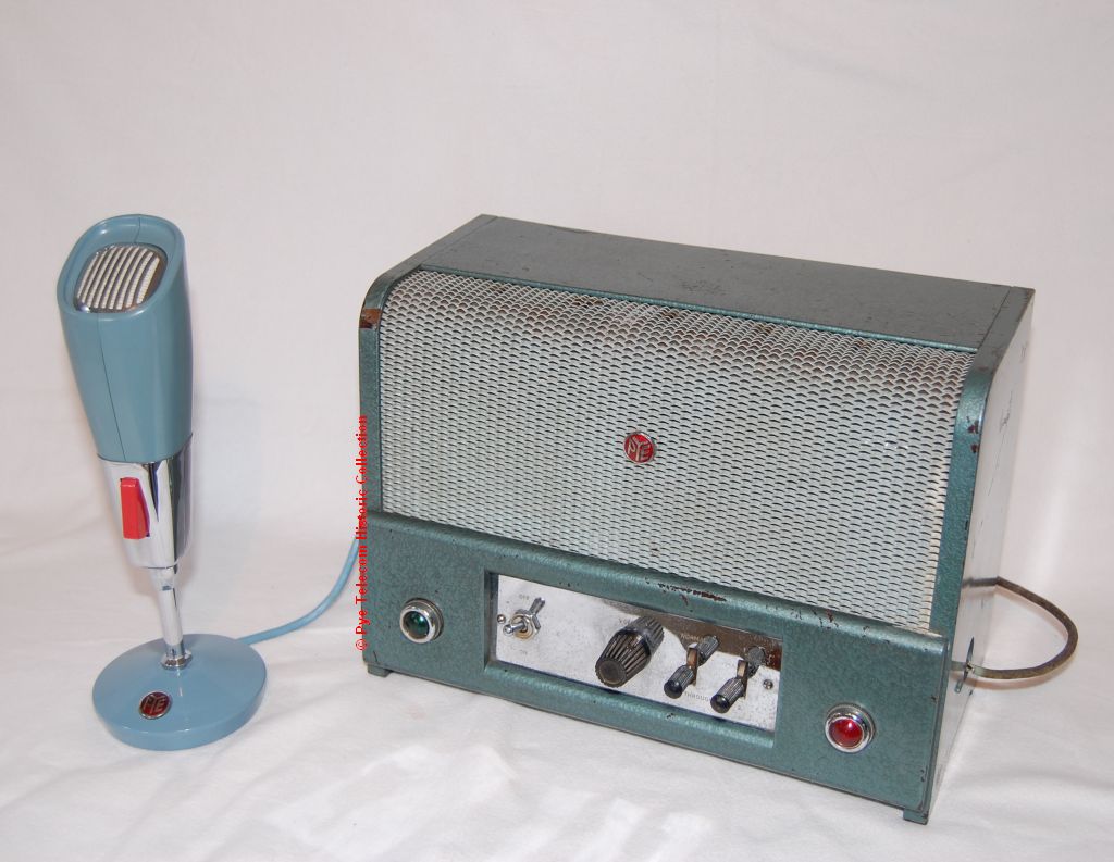 This
is a version of the existing PTC411 & PTC457/8
remote control equipment which used the new Pye
PTC4000 Series desk microphone instead of the
Lustraphone models. From December 1958 the use
of the Lustraphone desk microphones was discontinued
and the new PTC4000 Pye stand microphones (universally
known as the Tulip Mic) were supplied.
This change also applied to the following fixed
stations when locally controlled; PTC351/2/3/4,
PTC931, PTC723/4, PTC723/4YN (the PTC723 fixed station
used the PTC330 and PTC331 transmitter units). This
is a version of the existing PTC411 & PTC457/8
remote control equipment which used the new Pye
PTC4000 Series desk microphone instead of the
Lustraphone models. From December 1958 the use
of the Lustraphone desk microphones was discontinued
and the new PTC4000 Pye stand microphones (universally
known as the Tulip Mic) were supplied.
This change also applied to the following fixed
stations when locally controlled; PTC351/2/3/4,
PTC931, PTC723/4, PTC723/4YN (the PTC723 fixed station
used the PTC330 and PTC331 transmitter units). |
|||||||||||||||||||||||||||||
| Top of page | |||||||||||||||||||||||||||||
|
|
|||||||||||||||||||||||||||||
PTC431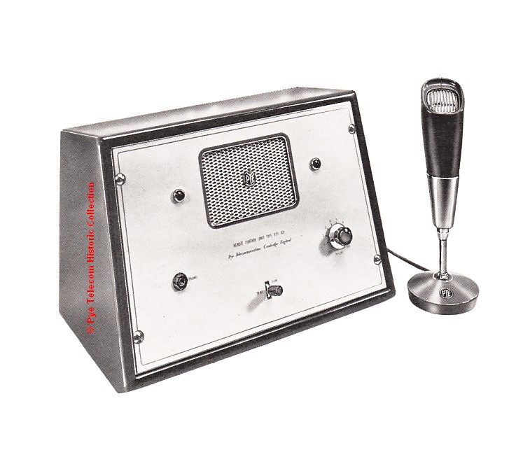 The
PTC431 controller was designed to provide control of a
VHF AM air-to-ground station where the transmitter and
receiver were sited separately. Two pairs of telephone
lines were used to connect to the VHF equipment which
could be sited up to 15 miles from the control operator
position. Although this controller was
specifically designed for use with the PTC3600 1 kWatt
transmitter used in trans-Atlantic ground-to-air
communication with aircraft in transit between
Newfoundland and Ireland, it was also adapted for use
with other systems where the TX and RX were sited
separately. The
PTC431 controller was designed to provide control of a
VHF AM air-to-ground station where the transmitter and
receiver were sited separately. Two pairs of telephone
lines were used to connect to the VHF equipment which
could be sited up to 15 miles from the control operator
position. Although this controller was
specifically designed for use with the PTC3600 1 kWatt
transmitter used in trans-Atlantic ground-to-air
communication with aircraft in transit between
Newfoundland and Ireland, it was also adapted for use
with other systems where the TX and RX were sited
separately. |
|||||||||||||||||||||||||||||
| Top of page | |||||||||||||||||||||||||||||
|
|
|||||||||||||||||||||||||||||
PTC957 & PTC958 remote control (HF)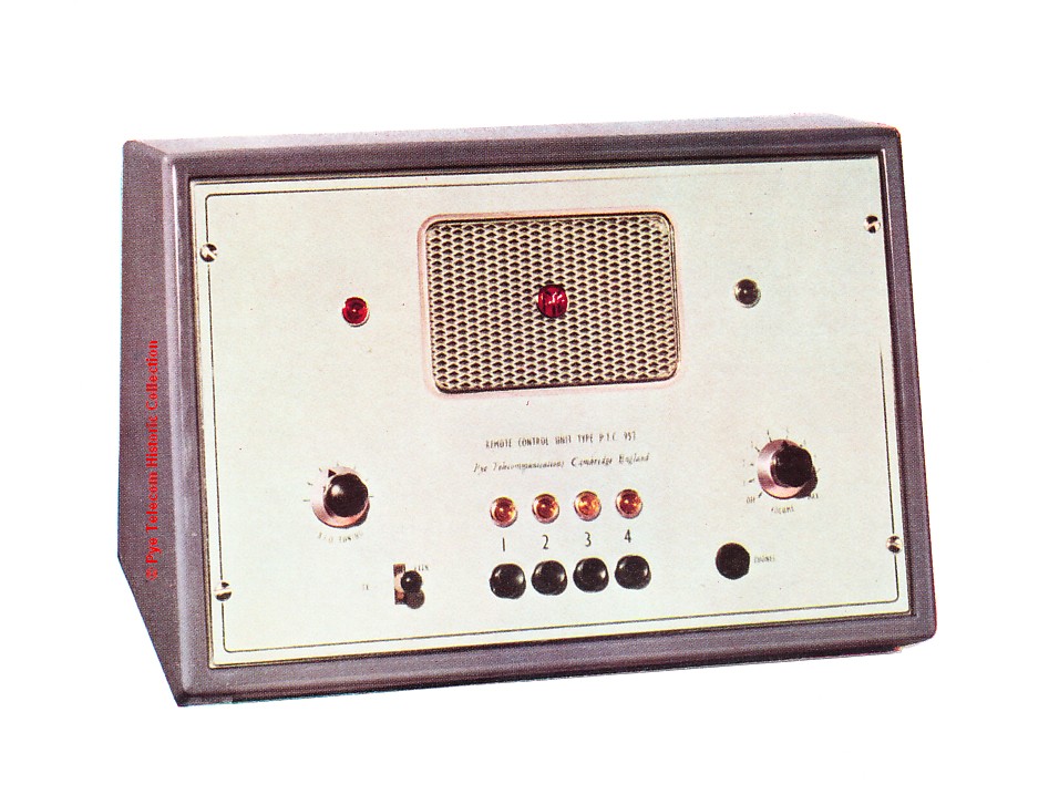 The PTC957 remote control
unit was designed to give operator control of the PTC790
60 Watt HF station over a distance of 15 - 20
miles. It provided send-receive switching, channel
selection and modulating facilities over one telephone
line, and with addition of a second line would also
remotely control the receiver Beat Frequency Oscillator
(BFO) to aid the reception of CW Morse code
signals. The PTC957 remote control
unit was designed to give operator control of the PTC790
60 Watt HF station over a distance of 15 - 20
miles. It provided send-receive switching, channel
selection and modulating facilities over one telephone
line, and with addition of a second line would also
remotely control the receiver Beat Frequency Oscillator
(BFO) to aid the reception of CW Morse code
signals. |
|||||||||||||||||||||||||||||
| Top of page | |||||||||||||||||||||||||||||
|
|
|||||||||||||||||||||||||||||
Custom Single Channel and/or Single Operator
Control Units (1950-1969)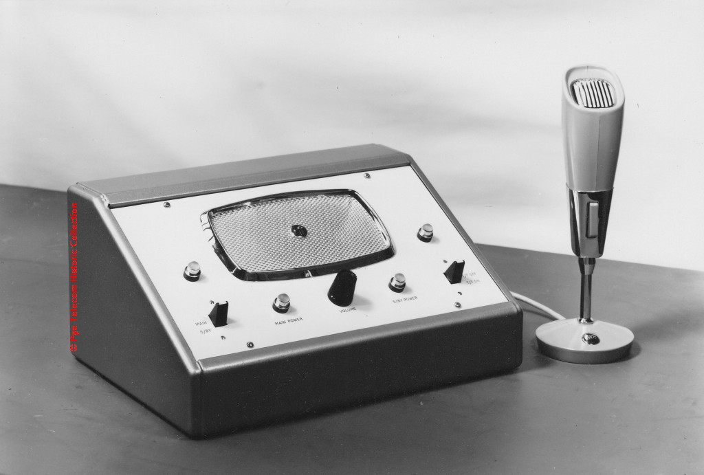 Although
the long running PTC411 single fixed station controller
was frequently modified for individual customer
requirements, many other physical and electrical
configurations were demanded by customers. This
led to the creation of small desk-top (or rack-mounted)
operator control panels, with much of the complex
electronics (termed common equipment) separately located
in a 19 inch rack cabinet. Although
the long running PTC411 single fixed station controller
was frequently modified for individual customer
requirements, many other physical and electrical
configurations were demanded by customers. This
led to the creation of small desk-top (or rack-mounted)
operator control panels, with much of the complex
electronics (termed common equipment) separately located
in a 19 inch rack cabinet.The example shown is a custom single channel desk-top controller from the 1960s. |
|||||||||||||||||||||||||||||
| Top of page | |||||||||||||||||||||||||||||
|
|
|||||||||||||||||||||||||||||
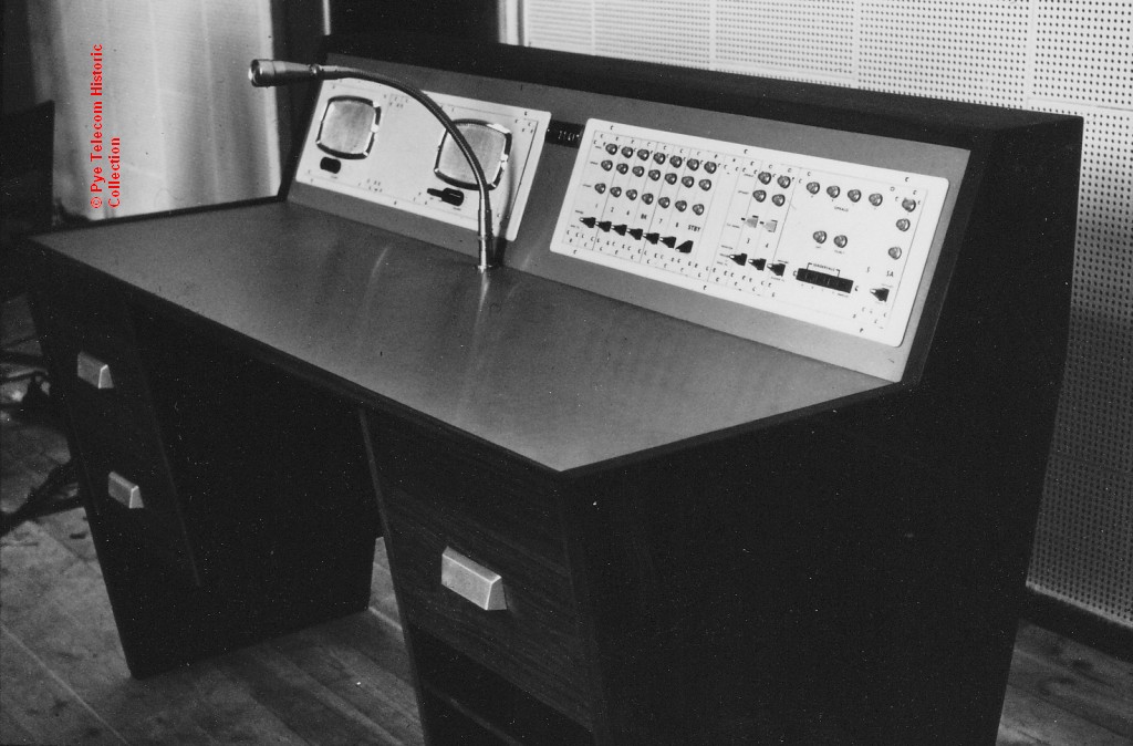
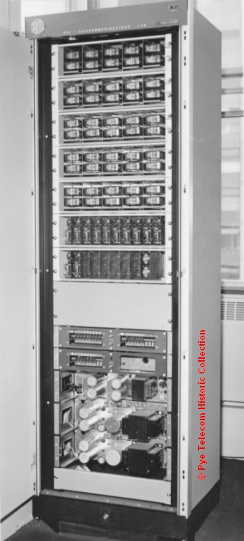
Custom Multi Channel and/or Multi Operator
Control Units (1950-1969)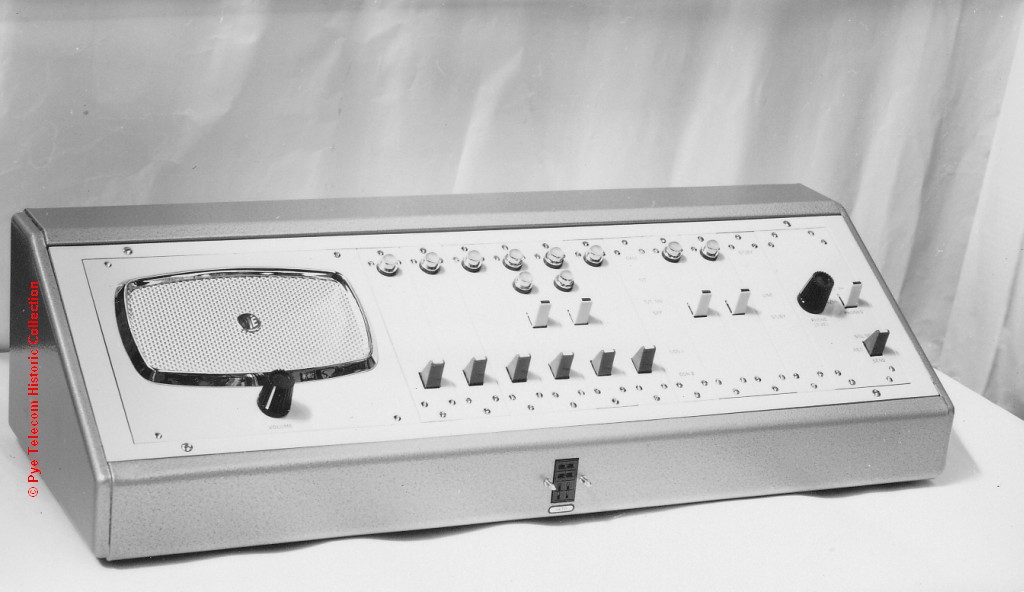 As
radio communications systems evolved through the 1950s
and 1960s, the need quickly developed for multi-channel
operation and multi-operator control. The
standard practice in the Radio Systems department at Pye
Telecom was to design custom radio systems to satisfy
the customer unique operational requirements and to
create custom operator control desks or consoles for
each one. Although designs were re-used and
gradually become modularised, they could not be
completely considered as standard products which could
be quickly priced and quoted without time consuming
design work. This practice resulted in a huge
number of different equipment variants. As
radio communications systems evolved through the 1950s
and 1960s, the need quickly developed for multi-channel
operation and multi-operator control. The
standard practice in the Radio Systems department at Pye
Telecom was to design custom radio systems to satisfy
the customer unique operational requirements and to
create custom operator control desks or consoles for
each one. Although designs were re-used and
gradually become modularised, they could not be
completely considered as standard products which could
be quickly priced and quoted without time consuming
design work. This practice resulted in a huge
number of different equipment variants.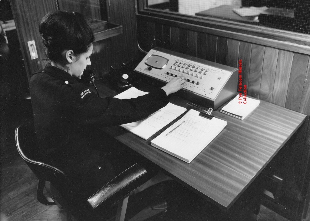 See example of an operator equipment desk and at right a desk-top console in use at a UK Fire and Ambulance Brigade in 1962. For complex multi-channel or multi-operator systems, which often included telephone-radio interfaces, a separate 19 inch rack of equipment would house the power supplies, line interfaces, switching equipment, dialling and ring-tone equipment, amplifiers etc. This was termed The Common Equipment. |
|||||||||||||||||||||||||||||
| Top of page | |||||||||||||||||||||||||||||
|
|
|||||||||||||||||||||||||||||
PT RTC Remote Controller and PT RTC (E) Extension
Controller (1963)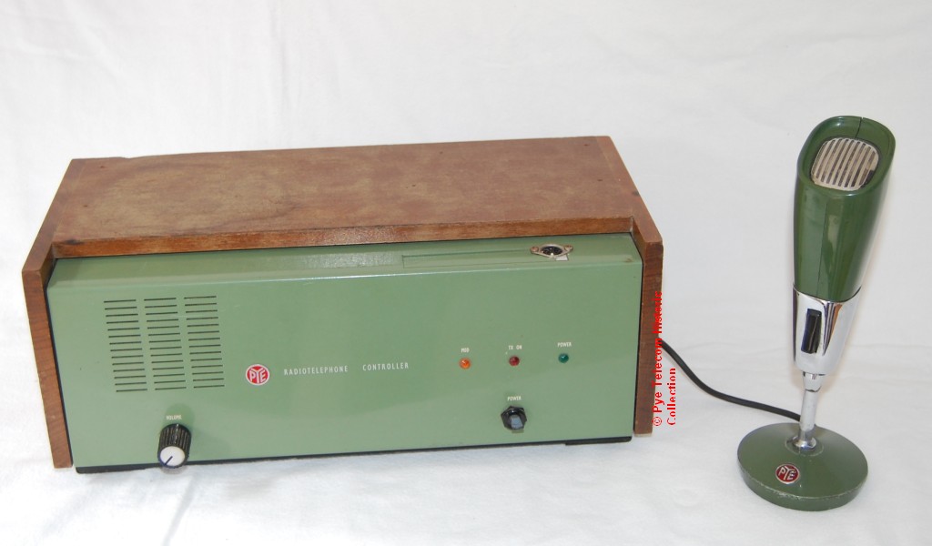 A long running series of
single channel control units designed by a team led by
Don Delanoy. The equipment came in two basic
variants, one for remote control of a fixed station
transmitter receiver and one for extension
control. The operator control instrument could be
the PTC4000 tulip mic, or a telephone handset. A long running series of
single channel control units designed by a team led by
Don Delanoy. The equipment came in two basic
variants, one for remote control of a fixed station
transmitter receiver and one for extension
control. The operator control instrument could be
the PTC4000 tulip mic, or a telephone handset.The equipment was replaced by the PC1, PC2, PC3, and PC5 series in 1971. |
|||||||||||||||||||||||||||||
| Top of page | |||||||||||||||||||||||||||||
|
|
|||||||||||||||||||||||||||||
5-Station Controller
(1963)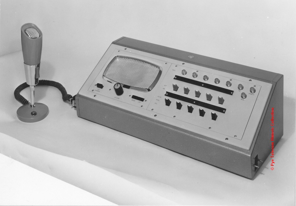 The
early 5-channel controller, which had limited up-grade
flexibility due to the design of the Common Equipment. The
early 5-channel controller, which had limited up-grade
flexibility due to the design of the Common Equipment.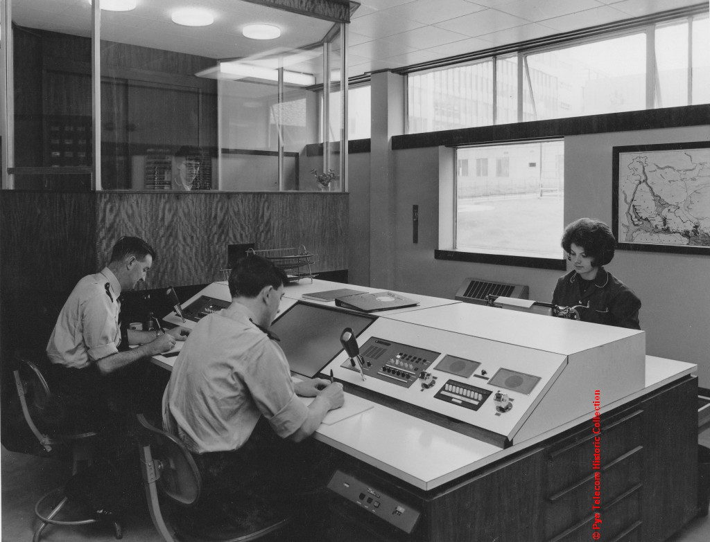 See image at right of the equipment mounted in control desk consoles in use with the Dumbartonshire Police circa 1967. |
|||||||||||||||||||||||||||||
| Top of page | |||||||||||||||||||||||||||||
|
|
|||||||||||||||||||||||||||||
5-Station Controller
(1969)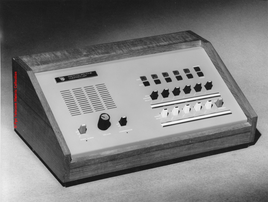 This
new design of 5-station radiotelephone controller was
introduced in 1969 to enable multi-channel radio This
new design of 5-station radiotelephone controller was
introduced in 1969 to enable multi-channel radio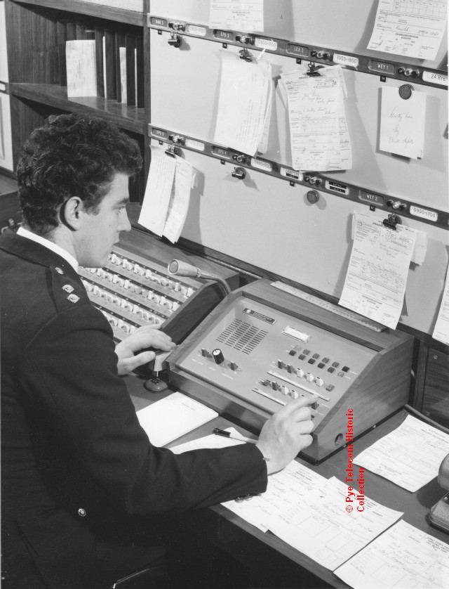 communications systems to be controlled using a standard
product, rather than create a custom design or variation
of a custom design for each major contract, as had been
done in the past.
communications systems to be controlled using a standard
product, rather than create a custom design or variation
of a custom design for each major contract, as had been
done in the past.An essential difference from earlier designs was that additional channel control modules could be added at any time to both the control desk equipment and to the rack of Common Equipment with which it interfaced. See image at right of the equipment in use with Surrey County Council Ambulance Service circa 1970. The equipment design was replaced by the Mascot 50 in about 1973. |
|||||||||||||||||||||||||||||
| To be continued |
|||||||||||||||||||||||||||||
| PC1, PC2, PC3, PC5 Series Controllers |
|||||||||||||||||||||||||||||
| UED6 Selcall Controller | |||||||||||||||||||||||||||||
Mascot Series Controllers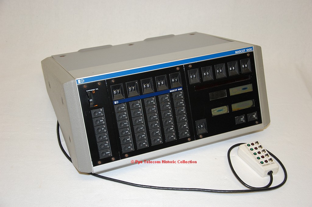 Mascot
M1000 Controller Mascot
M1000 Controller |
|||||||||||||||||||||||||||||
M80 Series Controllers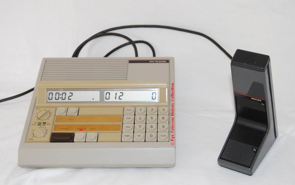 |
|||||||||||||||||||||||||||||
| RCU400 | |||||||||||||||||||||||||||||
| RCM4000 | |||||||||||||||||||||||||||||
| SRD1000 Desk-top
Controller |
|||||||||||||||||||||||||||||
|
Top of page
|
| Home
|
|
V2.0 - Date 04-10-2007 updated 02-06-2012 |
|
Copyright © reserved 2007-2012 Pye Telecom History Group, Cambridge, England |
